
Air venting solutions for micro-molding should be designed around where the flow front finishes, not added only after burn marks or short shots appear. In a tiny cavity, trapped gas occupies meaningful space, resists filling, and can heat rapidly as it is compressed. The correct venting plan gives air a controlled exit while keeping molten polymer inside the cavity.
This makes venting a balance problem. A path that is too restrictive leaves gas in the feature; a path that is too generous increases flash risk. Good results come from coordinating part geometry, gate location, vent position, surface condition, process settings, and maintenance.
The venting question in one sentence: Where will the final pocket of air go when polymer reaches the last functional feature?
Contents
Follow the Air Path Backward From the Last Fill Point

Start with the expected flow front. Gate position determines the order in which ribs, pockets, channels, and shutoffs fill. The last-fill location is often the first place to investigate when a feature is incomplete, discolored, or inconsistent.
Air may escape through a parting-line vent, an ejector clearance, a vented insert, a porous element, an overflow, or an actively evacuated cavity. The useful path depends on whether the gas pocket reaches the mold boundary. A blind micro pocket may need a local solution because a distant parting-line vent cannot remove air trapped behind an advancing flow front.
- Mark the gate and expected flow direction on the part drawing.
- Identify pockets where flow fronts converge or terminate.
- Check whether each pocket connects to a reliable escape path.
- Review whether the path remains open after thermal expansion and clamp load.
- Confirm that cleaning and maintenance can reach the venting feature.
Engineering judgment: a vent is useful only if air can reach it before the polymer seals the path.
Select the Venting Method by Location and Failure Mode
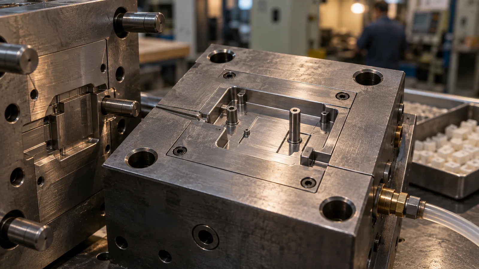
Not every cavity needs the same vent type. The choice should reflect where gas accumulates, how easily polymer flashes, and whether the vent can be serviced.
| Venting approach | Useful location | Main watchpoint |
|---|---|---|
| Parting-line vent | Accessible final-fill edge | Flash and contamination |
| Vented ejector or pin | Internal pocket near an ejector location | Wear, blockage, and witness marks |
| Vented insert | Local blind feature | Alignment and service access |
| Overflow well | Flow-front convergence or cosmetic boundary | Material loss and removal |
| Vacuum assistance | Complex trapped volumes or sensitive replication | Seal integrity and cycle integration |
Vacuum is not an automatic substitute for good geometry. If the cavity leaks, the evacuation path is poorly timed, or the gate seals before the trapped region is cleared, the additional system may add complexity without correcting the mechanism.
Balance Gas Release Against Micro-Flash Risk
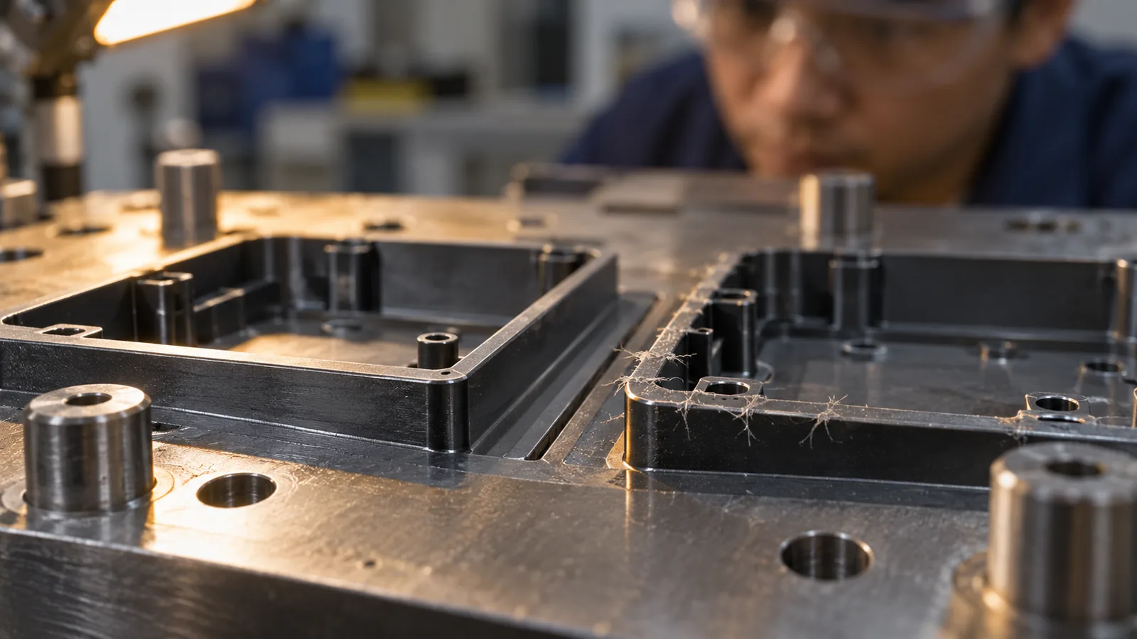
Vent dimensions cannot be selected from a universal number. Polymer viscosity, filler content, local pressure, mold temperature, vent land, steel condition, and feature location all influence whether melt enters the vent. A dimension that works for one resin and tool may flash with another.
The safe approach is to begin with the material, tool geometry, and expected cavity pressure, then validate through controlled trials. Vents should be shallow enough to retain polymer and sufficiently open to release gas. The transition from the shallow vent land to a larger exhaust path must also avoid creating another restriction.
Polishing the cavity does not necessarily improve venting. A highly polished shutoff may seal more effectively, while residue at the vent entrance can reduce the effective opening. Tool finish, contact pattern, and vent geometry should be reviewed as a system.
Do Not Use Process Settings to Hide a Tooling Limit

Higher melt temperature, mold temperature, or injection speed can delay freeze-off and improve replication. However, these changes may also increase flash sensitivity, residual stress, cycle time, or material degradation. When every acceptable part requires an extreme setting, the tool may lack a robust vent or flow path.
A quick distinction is to compare location and repeatability. A defect that always appears in one blind pocket or one cavity strongly supports a local tooling cause. A defect that moves between cavities or changes with material preparation may have a broader process source.
The Micro Injection Molding process requires the tool, material, filling profile, and metrology plan to work together. Venting should therefore be evaluated alongside gate placement and feature replication rather than as an isolated maintenance item.
Validate Venting With More Than Visual Inspection

Burn marks are obvious, but poor venting can exist without visible burning. Incomplete feature height, inconsistent part weight, pressure spikes, gloss changes, weak weld lines, and cavity-to-cavity variation can also reveal trapped gas.
- Create a defect map. Record the location, cavity, shot sequence, and orientation.
- Inspect the vent path. Check the entrance, land, exhaust channel, and final outlet.
- Compare pressure behavior. A sharp late-fill response can support a trapped-gas hypothesis.
- Clean before cutting. Confirm that residue, rust protection, or deposits are not reducing the opening.
- Run a controlled change. Modify one venting variable and compare repeated cycles.
- Measure the micro feature. Verify profile replication, not only overall fill.
Smoke, transfer marking, pressure data, short-shot studies, and cavity comparison can each contribute evidence. The right method depends on the tool and material, but the conclusion should never rest on a single attractive sample.
Keep the Vent Path Open During Production

Venting performance changes as deposits accumulate, surfaces wear, and maintenance practices vary. A tool that ran cleanly during qualification may develop trapped-air symptoms after thousands of cycles without any change to the approved settings.
Define inspection and cleaning intervals from actual buildup behavior. Record which vents are critical, what cleaning method is permitted, how the vent condition is verified, and when the tool must be stopped. Abrasive cleaning can alter a micro vent, while incomplete cleaning leaves the restriction in place.
Maintenance records become more useful when they reference the defect map. If a specific cavity repeatedly drifts before its scheduled cleaning interval, the plan should be adjusted around evidence rather than calendar habit.
Frequently Asked Questions

Can higher injection speed eliminate trapped air?
It may improve filling in some geometries, but it can also compress gas faster and increase local heating. Speed should be tested with the actual venting path rather than used as a universal fix.
Why does one cavity burn while the others look normal?
The affected cavity may have a blocked vent, a different last-fill location, local insert mismatch, or unequal flow balance. Compare its tool condition and pressure behavior with the remaining cavities.
Is vacuum venting always necessary for micro molding?
No. Conventional vents may be sufficient when air has a short, reliable escape path. Vacuum becomes more useful when geometry creates trapped volumes or replication remains sensitive despite a sound passive vent design.
How can vent cleaning cause flash?
Aggressive polishing or abrasion can enlarge the vent entrance or damage the vent land. Cleaning methods should remove deposits without changing critical steel geometry.
Should venting be reviewed before mold flow simulation?
They should support each other. Simulation can indicate likely final-fill and air-trap regions, while the tool design must convert those locations into manufacturable, maintainable escape paths.