
A valve seat may need a compliant, low-friction surface, while the body must retain its geometry under pressure. Choosing one polymer for both jobs can create an avoidable compromise. PEEK vs PTFE is a choice between two different jobs. PEEK is a melt-processable structural thermoplastic that can carry load and hold geometry at elevated temperature. PTFE is selected for chemical inertness, very low friction and non-stick behavior, but conventional PTFE does not melt-flow like PEEK and is not processed by standard injection molding.
In this article:
- Why the manufacturing route matters
- Load and creep
- Friction and wear
- Chemical exposure
- Cost and validation
The first difference is how the part is made
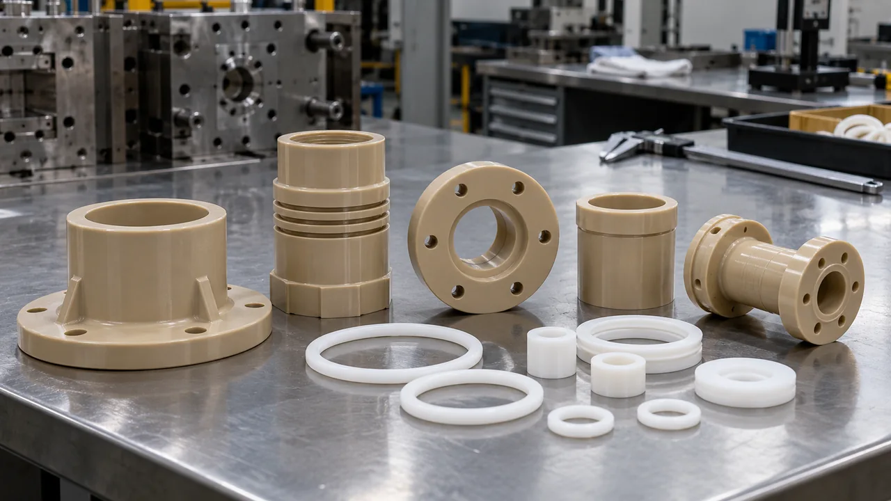
PEEK softens into a processable melt and can be injection molded into complex production parts. Conventional PTFE has an exceptionally high melt viscosity; common PTFE components are formed from powder by compression, sintering and machining. Melt-processable fluoropolymers exist, but they are not interchangeable with standard PTFE. PEEK injection molding supports ribs, bosses and consolidated features, while conventional PTFE production often begins with a compressed billet or near-net preform. That difference changes achievable detail, material waste and the economics of revisions. Compare a complete drawing and annual demand with suppliers from both manufacturing routes. A purchaser comparing molded PEEK with machined PTFE must include the number of setups, stock allowance and inspection operations.
This manufacturing difference affects every cost calculation. Injection-molded PEEK may require expensive tooling and high processing temperatures, yet it can consolidate features and scale efficiently. PTFE may avoid an injection mold but require stock preparation, machining, material removal and secondary inspection. An intricate body with ribs and assembly features may benefit from molding, while a simple seal produced in small quantities may not justify tooling. Treat the manufacturing route as part of the design decision. Conventional PTFE, modified PTFE and melt-processable fluoropolymers need separate identification; a supplier’s broad fluoropolymer label is not sufficient.
What happens when the part carries load?
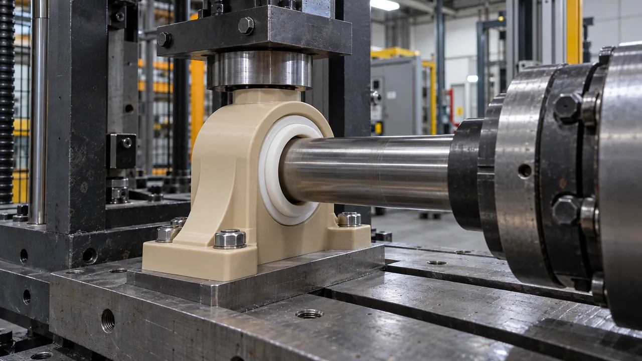
PEEK is normally favored for structural brackets, gears, electrical components and precision bodies because it retains stiffness and resists creep more effectively under load. PTFE can cold-flow over time, especially when pressure and temperature act together. A PTFE seal may use that compliance advantage; a locating feature may lose alignment because of it. PTFE deformation depends on contact stress, temperature and duration, not simply on overall part load. A wide seal land may work well while a narrow locating shoulder creeps enough to lose alignment. Calculate local bearing pressure and measure retained position after a timed hot-load test. Examine the geometry carrying the force.
Do not compare tensile strength alone. Review compressive stress, contact area, time, temperature and whether a fastener maintains preload. A broad supported seat distributes pressure differently from a narrow shoulder or threaded feature. PTFE’s compliance can help a sealing surface conform, but progressive movement can undermine a precision locator. Reinforced PEEK also requires verification at weld lines and across the flow direction. Compare displacement after the required dwell period and temperature cycle, then check whether the assembly still holds its alignment or seal.
Where PTFE has the clearer advantage
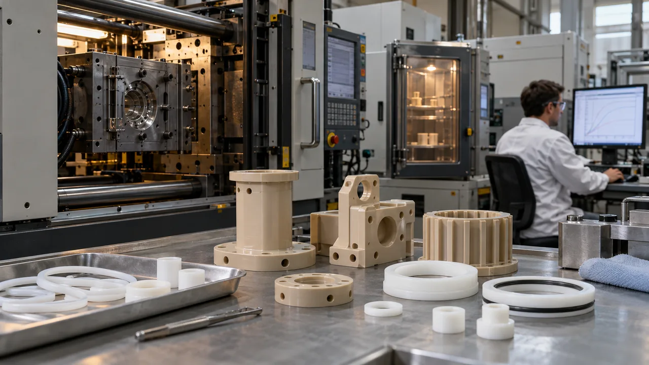
PTFE is the natural starting point for low-friction sliding surfaces, chemically inert liners, valve seats and release applications. PEEK can also be compounded for wear and friction, and it is more suitable when the same component must carry significant structural load. Wear is a system property involving polymer grade, counterface hardness, roughness, speed, pressure, lubrication and contamination. Low initial friction does not guarantee low long-term wear or dimensional stability. Run the intended motion and duty cycle against production-equivalent counterfaces. Breakaway friction, running friction and wear rate answer different questions.
The counterface, lubrication, pressure-velocity condition and debris tolerance determine real wear behavior. A generic coefficient from a datasheet cannot replace a tribology test using the intended surface finish and motion. A part that starts easily may still wear rapidly under repeated motion or contaminated service. Filled PTFE and bearing-grade PEEK can behave differently from their unfilled versions, so the grade and mating metal are inseparable from the result. Include counterface finish, motion type, lubrication and operating temperature in the test request, and inspect both the polymer and its mating surface afterward. Some designs need PTFE only at the interface and structural stiffness elsewhere. A replaceable PTFE element, filled PEEK bearing grade or mechanically retained liner can allocate each function without over-specifying the full component. Evaluate assembly retention, differential expansion and service replacement before choosing a hybrid route. Chemical inertness alone does not define a pressure boundary.
PEEK and PTFE by failure mode
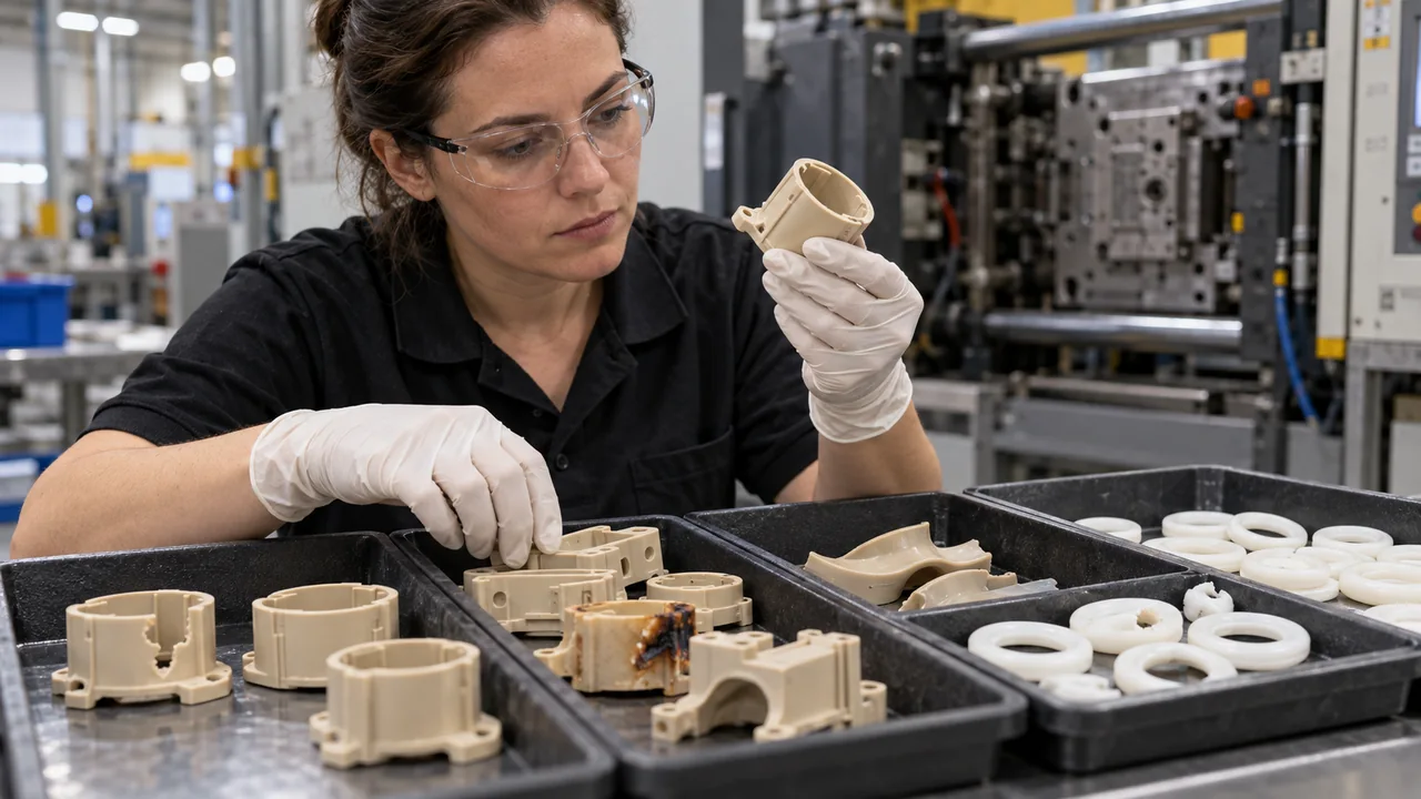
| Failure to prevent | Better starting point | Validation needed |
|---|---|---|
| Creep or loss of position | PEEK | Load-duration-temperature test |
| High breakaway friction | PTFE | Counterface and PV test |
| Structural fatigue | PEEK | Notches, weld lines and cycles |
| Broad chemical inertness | PTFE | Permeation, pressure and temperature |
When injection molding changes the answer
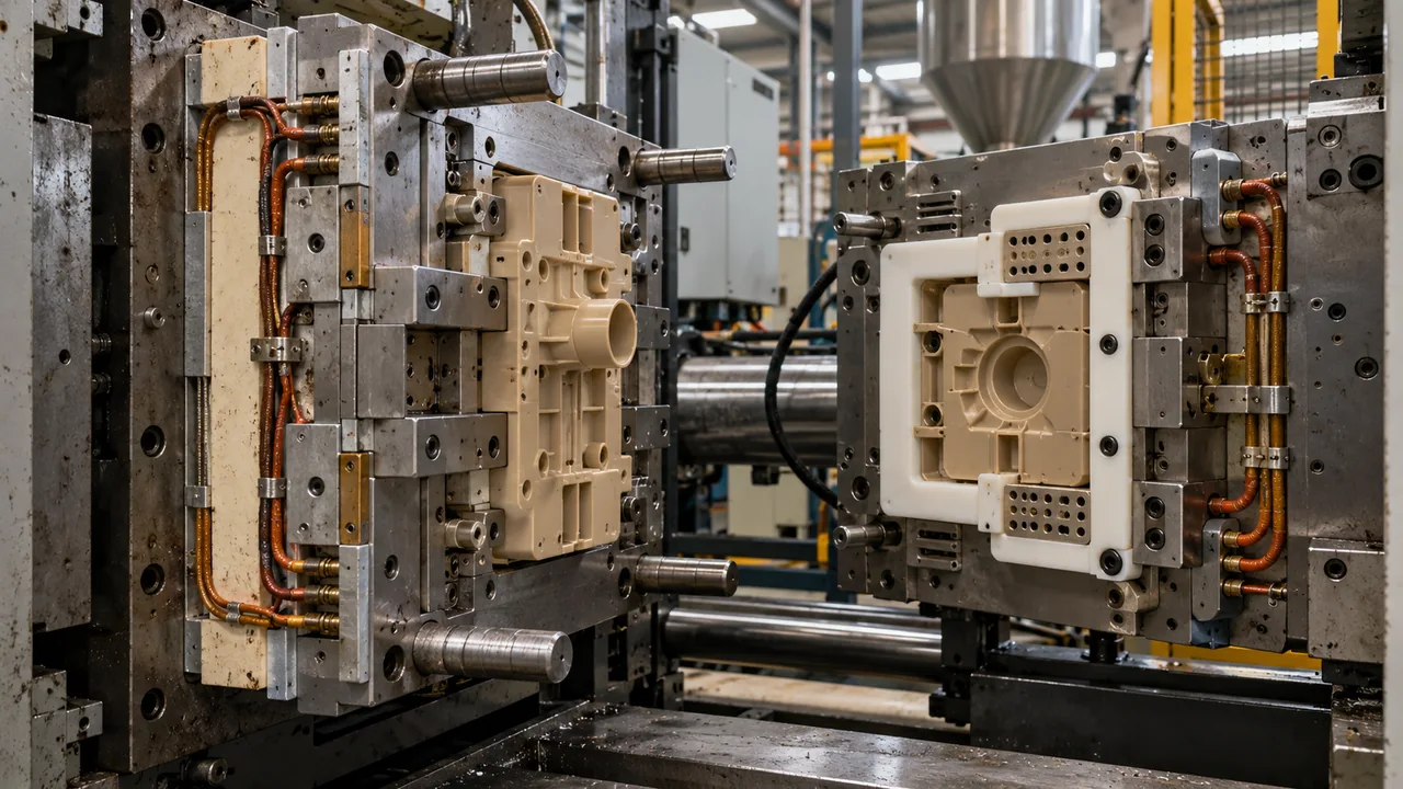
If annual volume, geometry and feature consolidation favor injection molding, PEEK may reduce assembly and machining operations. It still requires a suitable High-Temperature Polymer Molding cell and careful control of crystallinity, gates and thermal balance. The available PEEK material grades include unfilled, glass-filled, carbon-filled and medical options with different behavior. The review also needs permeation, leakage at joints, support against deformation and compatibility of fillers or adjacent seals. Where PEEK supplies the structure and PTFE supplies a contact surface, evaluate how the insert or liner is retained as temperatures change. A hybrid component is an engineering option, not an automatic improvement; assembly labor, interface movement and replacement requirements can reverse its cost advantage. PEEK tooling becomes attractive when molding removes machining setups, drilled passages or multi-piece assembly. For low volume and simple geometry, machined PTFE may still have the lower entry cost. Model tooling amortization, expected yield and inspection time at realistic annual quantities. For a molded body, identify features that would otherwise need drilling, machining or joining.
If PTFE remains necessary for the contact surface, consider whether a two-component assembly, insert, liner or bearing element can separate the low-friction function from the structural body. That can avoid forcing one polymer to solve incompatible requirements. This allows tooling investment to be compared against actual eliminated operations. For a PTFE contact element, decide whether it is captive, replaceable or bonded, and confirm the interface at temperature. The assembly should keep structural loads away from an unsupported low-friction layer. Feature consolidation only counts as a benefit after the finished assembly passes its functional tests.
Compare finished-part cost, not resin price
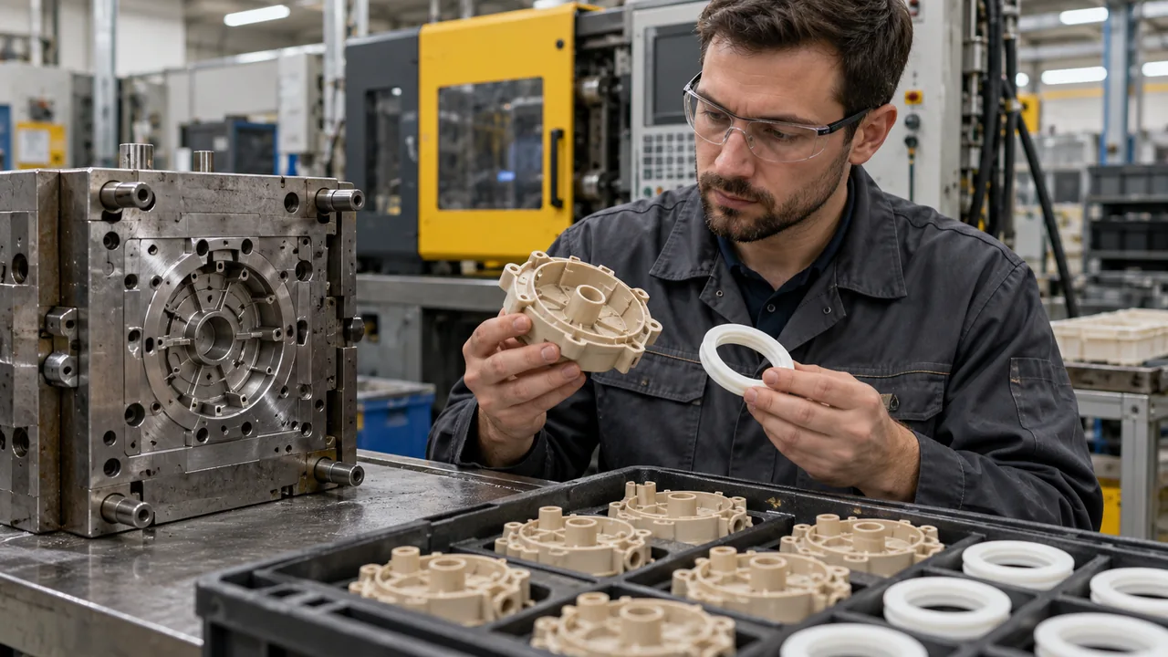
Include material utilization, mold investment, machining time, inspection, rejected parts and assembly. Also price the failure mode: replacing a creeping precision component can cost more than the initial material difference. A low-friction material that creeps can increase leakage or adjustment frequency, while a stiff material with excessive friction can accelerate counterface wear. Either field outcome can dominate purchase price. Include maintenance interval, downtime and replacement access in the total-cost review. Request cost at several realistic annual quantities and include the cost of material removed during machining. For molding, include tool life assumptions, qualification, startup losses and inspection. For a seal or sliding element, add replacement interval and access labor where those costs are known. Do not assume that the cheaper kilogram price produces the cheaper component: yield, geometry and service behavior determine the finished-part comparison.
Frequently asked questions
Can PTFE be injection molded like PEEK?
Conventional PTFE is generally compression molded, sintered and machined because it does not flow like a normal melt-processable thermoplastic. Some modified fluoropolymers use different processes. Ask which fluoropolymer and manufacturing route are being quoted. Powder processing, machined stock and melt-processable fluoropolymers create different geometry and cost assumptions.
Which is better for a bearing?
PTFE favors very low friction; PEEK favors load capacity and dimensional stability. Bearing pressure, speed, temperature and counterface decide the answer. Include pressure, speed, lubrication and counterface finish in the test. Filled bearing grades should be evaluated separately, since the filler package changes friction and wear behavior.
Which material is better for chemical service?
PTFE has exceptionally broad inertness, but PEEK combines strong chemical resistance with structural performance. Test the exact fluid, concentration, temperature and stress. Check the loaded assembly as well as chemical compatibility. Permeation, deformation and seal support may determine service reliability before visible attack of the base polymer occurs.