
A micro injection molding tolerance stack explains why individually acceptable features can still produce a loose, tight, misaligned, or nonfunctional assembly. At small scale, datum construction, cavity variation, directional shrinkage, insert position, measurement uncertainty, and mating-part error can consume clearance quickly.
The practical solution is to build the stack around the function, separate sources of variation, and verify the model with assembled evidence. Tightening every drawing dimension usually increases inspection and tooling burden without guaranteeing fit.
Contents
A Tight Dimension Can Still Produce a Loose Assembly
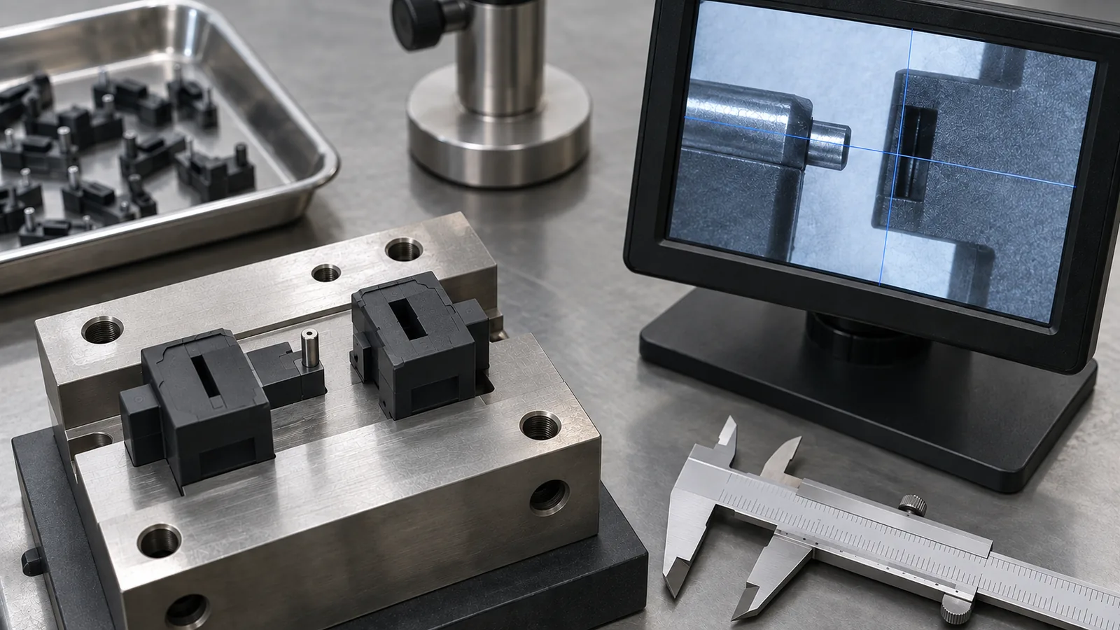
Consider a micro pin entering a mating slot. Fit depends on pin size, slot size, their positions from functional datums, angular error, part warpage, and how both pieces are restrained. A narrow size tolerance cannot compensate for a positional datum that does not match the assembly.
Start with the functional output: clearance, interference, seal compression, gear center distance, optical alignment, connector pitch, or channel registration. Then trace every contributing dimension. Features that do not materially affect the output should not receive the same tolerance burden.
Temperature and conditioning belong in the stack when the assembly experiences them. A dimension measured immediately after molding can differ after moisture uptake, annealing, sterilization, or operating heat.
Build the Stack From Functional Datums
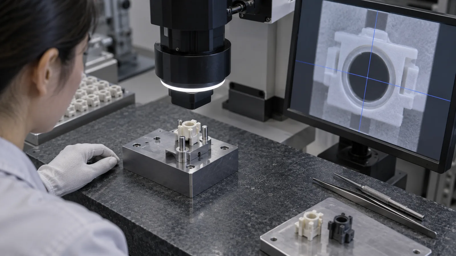
Datums should reproduce how the part is located in the product. If a housing sits on three pads and is positioned by a bore, measuring from an unrelated exterior edge creates a result that may be repeatable but irrelevant.
Map the chain through the tool as well. Cavity insert location, core pin, slide, shutoff, and insert fixture can contribute to a finished relationship. A dimension controlled by two independently installed components will normally require a different strategy from one machined into the same insert.
- Define the assembly output and acceptable range.
- Select product datums that match real constraint.
- List every contributor with direction and sign.
- Identify which contributors share a tooling datum.
- Add conditioning and measurement uncertainty where relevant.
- Compare the predicted stack with assembly trials.
Separate Tool, Process, Material, and Measurement Error
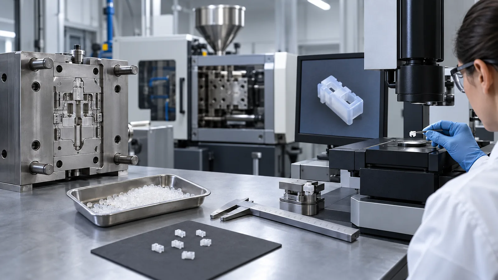
Variation from steel geometry behaves differently from variation caused by filling or cooling. A fixed cavity offset may remain stable until wear or maintenance. Process-driven dimensions can shift with material lot, thermal balance, packing, or cycle conditions. Measurement adds another layer through fixture, focus, edge selection, and operator method.
| Source | Typical pattern | Best first evidence |
|---|---|---|
| Tool geometry or alignment | Stable offset in one feature or cavity | Cavity map and tool-component inspection |
| Process and cooling | Drift with thermal or pressure history | Time sequence and process signals |
| Material and conditioning | Lot, moisture, or time-dependent change | Material records and conditioned samples |
| Measurement system | Operator, fixture, focus, or method disagreement | Repeatability and reproducibility study |
A quality control plan should identify these sources instead of reporting only a pooled pass rate.
Use Worst-Case and Statistical Thinking Carefully
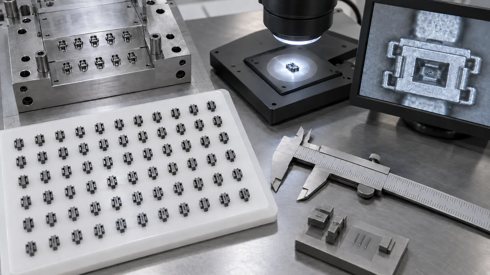
A worst-case stack adds contributors at their limiting conditions. It is appropriate when every permitted combination must assemble, but it can produce a wide predicted range and expensive individual tolerances. A statistical stack estimates likely combined behavior when contributors are stable and sufficiently understood.
Statistical treatment is not permission to ignore cavity bias, drift, or non-normal behavior. If one cavity has a fixed offset, pooling it with the others can make the process look wider and hide the corrective opportunity. If a feature distribution changes with conditioning, one capability number may not represent use.
Use the method that matches risk, volume, control, and consequence of failure. State the assumptions clearly. For a critical interference or safety-related function, direct assembly testing may still be required even when the dimensional model looks favorable.
Control Cavity-to-Cavity Differences
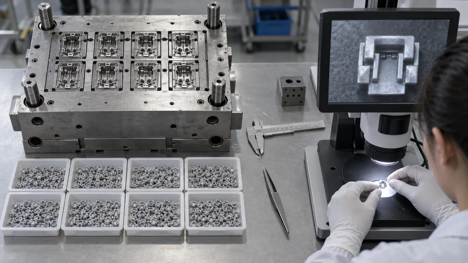
Each cavity is a distinct combination of steel geometry, gate condition, venting, cooling, and local filling history. Traceability by cavity is essential during qualification. If data are pooled too early, an outlying cavity can be mistaken for random process noise.
Balance does not mean every measured value is identical. The goal is for each cavity to remain within its validated window and for the combined output to meet assembly requirements. Steel adjustments, gate balancing, or cavity-specific maintenance may be appropriate when a systematic difference is confirmed.
The precision injection molding tolerance guide provides broader context for process capability; the stack still needs to be built for the specific assembly.
Close the Loop With Assembly Evidence
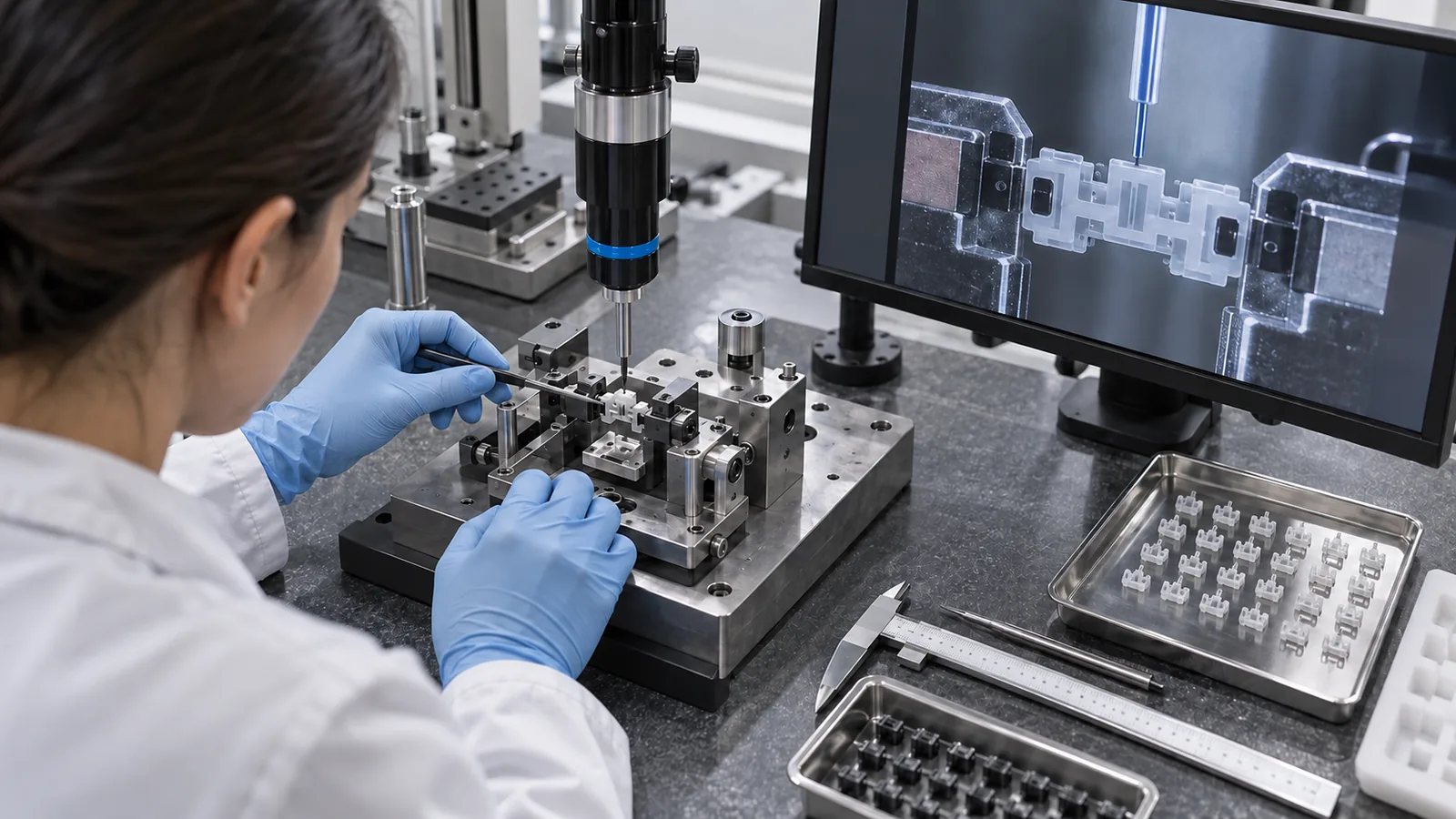
Measure representative components, assemble them using the intended fixture and sequence, and record the functional result. If the model predicts fit but assembly fails, inspect datum simulation, part restraint, deformation, mating-part variation, and measurement correlation.
Use boundary samples where possible. Parts near dimensional limits reveal whether the functional requirement has been allocated correctly. Temperature, moisture, sterilization, load, and aging should be included when they affect the relationship.
A robust Micro Injection Molding program links cavity-specific process evidence, metrology, handling, and assembly validation. That evidence turns a tolerance stack from a spreadsheet assumption into a production control.
Revisit the stack after the first representative tool trial. Replace assumed contributors with measured cavity and assembly data, then confirm that any drawing change still protects function across normal production conditions.
Frequently Asked Questions

Should every contributor use its drawing limit in a worst-case stack?
Use the limits and datum rules that actually govern acceptance, but verify whether the part is constrained or conditioned differently in assembly.
Why can capability look good while assemblies fail?
The measured feature may not control the function, pooled data may hide cavity offsets, the datum simulation may differ, or the mating-part contribution may be missing.
Can measurement uncertainty be ignored?
No. When uncertainty is large relative to tolerance, apparent part variation can reflect the method. The measurement system must be qualified.
How should multi-cavity data be reported?
Keep cavity identity through qualification and review both individual cavity behavior and combined output.
When should statistical stacking be used?
Use it when contributor distributions are stable, independent assumptions are defensible, and the product risk allows a probability-based decision.