
Flow marks in injection molding often return because a process change moves the visible line without removing the mechanism. The mark may record a cold flow front, hesitation, gate jetting, unstable velocity, thickness transition or surface replication difference. To correct it permanently, relate the mark to fill position and geometry before changing temperature or speed.
Fastest useful test: make a short-shot sequence and overlay the visible mark on the advancing flow front. If the mark follows a hesitation or reacceleration point, the part geometry and velocity profile are already telling you where to investigate.
In this article:
- Identify the mark family
- Find the geometric trigger
- Stabilize the flow front
- Check surface and thermal replication
- Verify across a process window
- Frequently asked questions
Not Every Line on the Surface Is the Same Defect
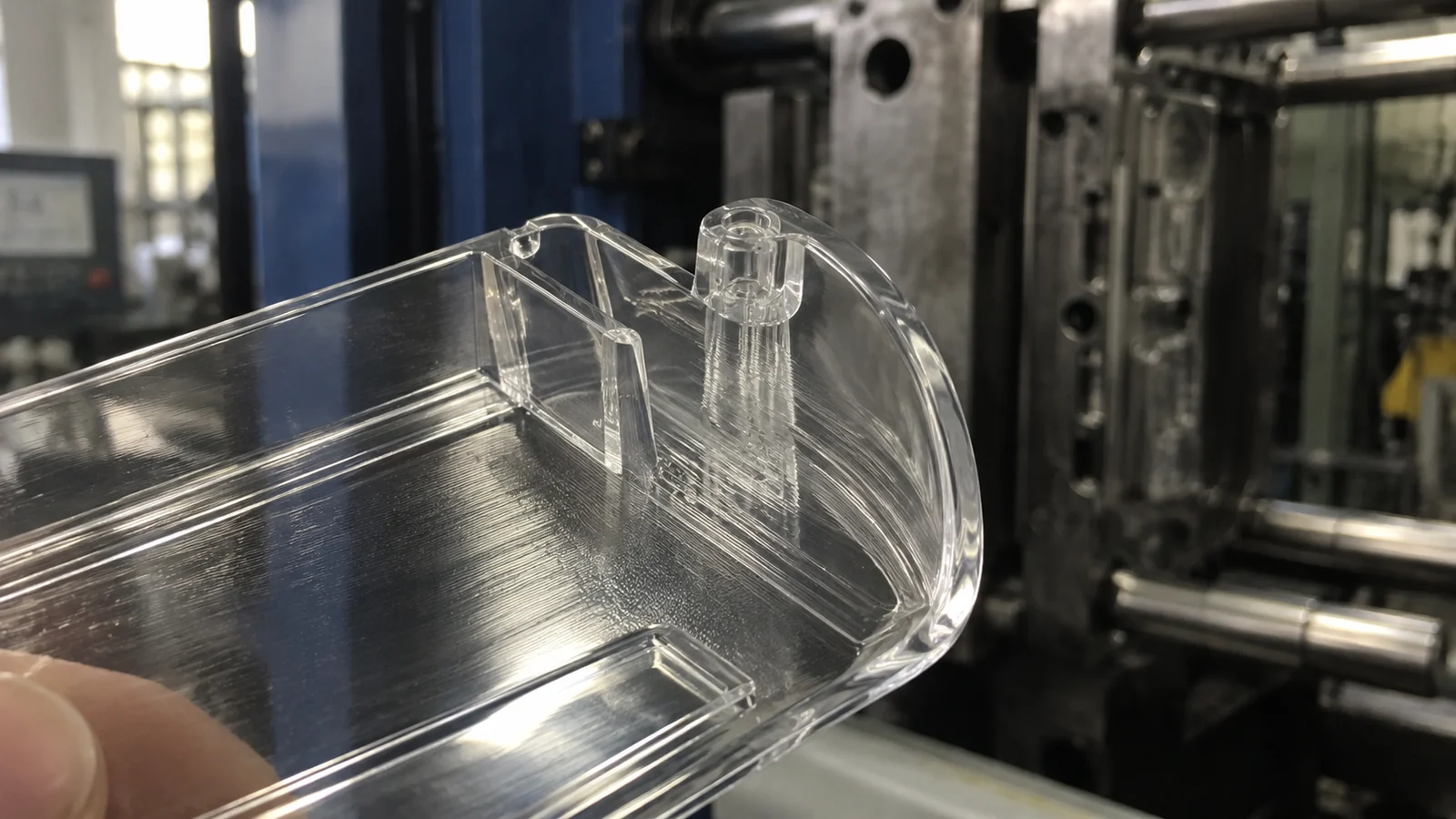
A repeating wave near the gate may indicate jetting or unstable initial flow. A line after a rib or sudden expansion may record hesitation. A dull-to-glossy boundary can come from a change in surface contact or flow-front temperature. A weld line forms where fronts meet and needs a different correction path.
Inspect both sides of the part and compare cavities. Note whether the line is raised, depressed, different in gloss or only visible under certain lighting. On clear parts, also view transmitted light because a subtle surface or orientation change may be stronger optically than cosmetically.
The Mark Often Begins Where Flow Loses Momentum
Abrupt thickness changes, thin-to-thick transitions, ribs, bosses and large open regions change local velocity and cooling. Melt can hesitate in a thin branch while another region fills, then restart with a colder skin. That restart may remain visible as a boundary.
Round transitions where function allows, keep wall changes gradual and avoid a gate that fires into open space without wall contact. A gate relocation can improve one surface while moving a weld line into the optical path, so evaluate the complete fill pattern.
Control Velocity at the Defect Location, Not Only at the Machine
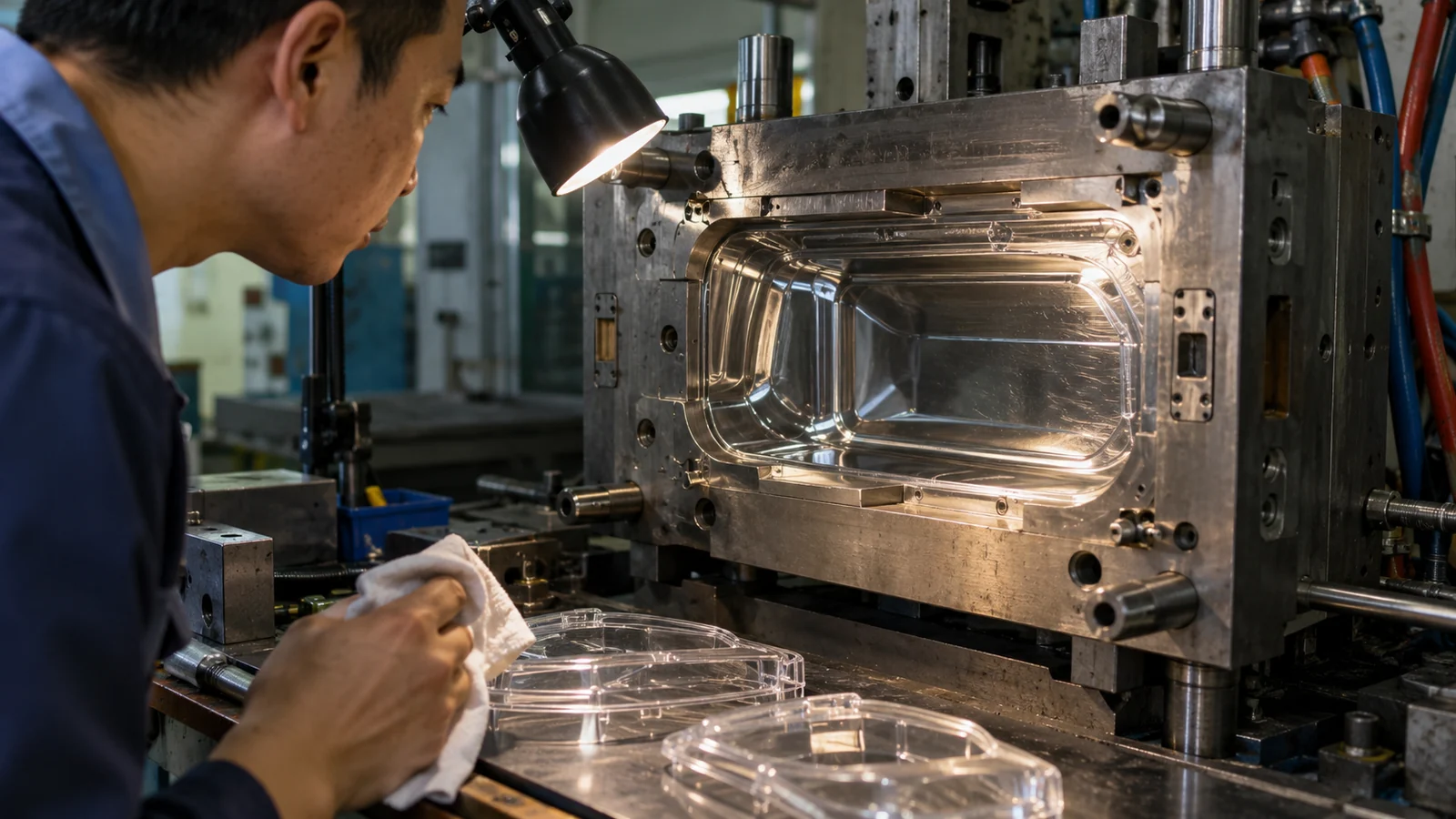
Machine screw speed is not the same as flow-front velocity. As the cavity’s projected flow area changes, the front can accelerate or slow even at a constant programmed speed. Use staged filling based on screw position and short-shot evidence to manage the critical transition.
Melt and mold temperature influence how long the surface remains able to replicate the steel. Raising them may improve a cold mark, but it also changes cycle, shrinkage and degradation risk. Confirm actual melt and mold conditions and stay within the resin supplier’s processing window.
Surface Finish Can Reveal a Thermal Boundary
A polished optical face shows small differences in replication. Uneven mold temperature, contamination, vent deposits or local steel texture can make a flow boundary visible. Clean and inspect the cavity before building a complex process correction around a damaged surface.
Venting matters at the region where air is compressed. Restricted vents can change surface contact or create burns and deposits. A vent correction should be confirmed for flash risk across the allowed pressure window.
A Cosmetic Fix Must Survive Normal Variation
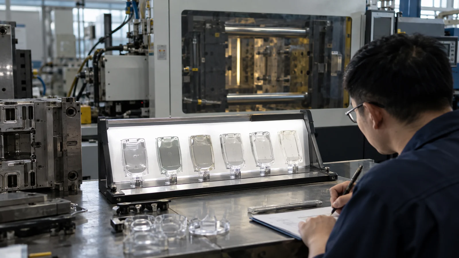
Once the mark improves, test the solution across realistic material lots, cavities, mold temperatures and cycle interruptions. Track the same lighting and viewing standard. A setting that hides the mark only at one high temperature is not robust production control.
For Optical & Clear Injection Molding, add transmitted-light or functional checks where the part guides, images or distributes light. A visually acceptable boundary can still alter the optical path.
| Evidence | First hypothesis | Next check |
|---|---|---|
| Waves immediately after gate | Jetting or unstable entry | Gate direction and initial velocity |
| Line after thickness change | Hesitation or reacceleration | Short shots and staged fill |
| One-cavity gloss boundary | Local surface or temperature issue | Cavity, vent and cooling inspection |
Define visibility before optimizing it away
Agree on the light source, angle, background, viewing distance and inspection zone. A line invisible under diffuse room light may be obvious under a dashboard backlight or sunlight. Stable inspection conditions prevent a process from being adjusted to one person’s viewing angle.
When sending a part for troubleshooting, include short shots, an untrimmed sample, cavity identity, gate and wall-thickness information, resin grade and the settings from good and bad periods. The contrast between those periods is often more useful than a single nominal setup sheet.
Distinguish a robust correction from a cosmetic mask
Texture, coating or tint can reduce visibility, but it may only mask a flow instability. If the mark also represents stress, weak welding or poor replication, hiding it does not resolve function. Confirm dimensional and mechanical results before accepting a cosmetic secondary operation as the permanent answer.
A robust correction should remain effective through startup, nominal production and expected variation in resin lot, mold temperature and cycle. Document the short-shot evidence and the mechanism that changed. That record helps future technicians recover the process without repeating random adjustments.
Frequently Asked Questions
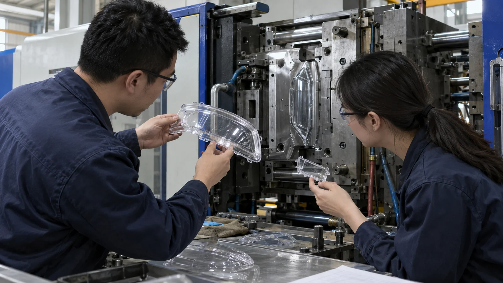
Will faster injection always remove flow marks?
No. It may keep the front hotter, but it can also create jetting, shear or trapped gas. Match velocity to the defect location.
Can polishing the mold remove the mark?
Only if surface condition is the cause. Polishing does not correct hesitation, gate jetting or an unstable thermal boundary and can change optical form.
Why does the mark return after maintenance?
Cleaning, reassembly, cooling connection, vent condition or hot-runner balance may have changed. Compare cavity and process records before and after the event.