
Tight dimensions can still fail optically because optical injection molding tolerances must control relationships, not isolated numbers. A lens can meet diameter, thickness and flatness limits while its optical axis is decentered from the mounting datum. A clear window can pass a profile check and still distort an image through local form error or molding stress.
Better starting point: define the optical output and its mechanical reference, identify which variation changes that output, then assign tolerances and inspection methods to those contributors.
In this article:
- Start with functional error
- Build a useful datum scheme
- Create a tolerance budget
- Match measurement to the feature
- Use capability without hiding cavities
- Frequently asked questions
Convert Optical Failure Into Measurable Contributors
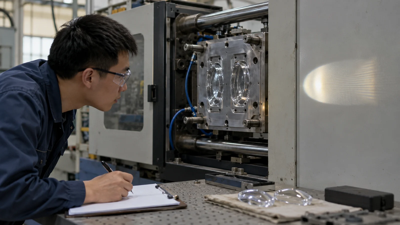
For an imaging optic, the unacceptable result might be blur, distortion or focal shift. For a light guide, it may be brightness nonuniformity or crosstalk. For a protective window, it may be transmitted wavefront error or visible distortion. Each result responds to a different mix of geometry, material and stress.
Use sensitivity analysis where possible: vary one contributor in the optical model and observe the output. This reveals whether center thickness, curvature, decenter, tilt or surface form deserves the tightest control. It also prevents money being spent on dimensions with little functional leverage.
The Datum Scheme Must Survive Assembly

Choose datums that represent how the part is located in the product. If inspection centers a lens on its optical surface but assembly locates it by three plastic pads, the two conditions may not agree. Relate the optical axis or clear aperture to the actual mounting features.
Avoid overconstraining flexible parts during measurement. A fixture that forces a warped window flat can report an acceptable profile that does not exist in free state. Conversely, an assembly may intentionally constrain the part; in that case, define the controlled condition and reproduce it consistently.
Budget Error Across Mold, Process and Assembly
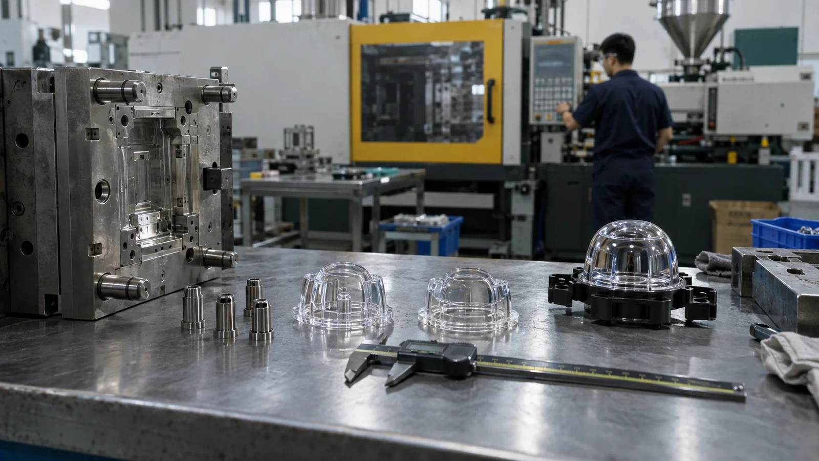
The final optical alignment includes cavity geometry, insert location, molded shrinkage, ejection change, conditioning, housing variation and assembly load. Assigning the complete allowable error to the molded part ignores the rest of the stack. Assigning an unrealistically small share to molding may create inspection disputes without improving the product.
| Contributor | Typical question | Control route |
|---|---|---|
| Optical insert | Is form or position changing? | Insert metrology and cavity traceability |
| Molding process | Does shrinkage remain stable? | Window study and part capability |
| Assembly | Does retention tilt or stress the optic? | Assembly gauge and functional test |
One Instrument Cannot Prove Every Requirement
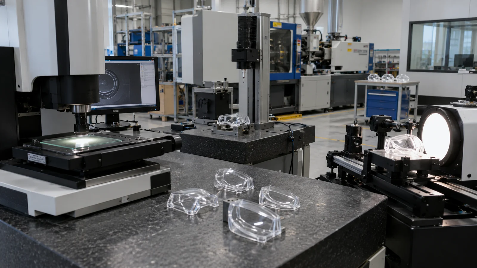
A contact gauge may be suitable for an outer diameter but damage or deform an optical face. A vision system can measure edges and datums but may not capture three-dimensional surface form. Interferometry, profilometry or other optical metrology may be required for critical surfaces, while a functional bench verifies the final beam or image.
Define fixture, orientation, temperature, conditioning time, filter settings and data reduction. Without a common method, two laboratories can report different values for the same part. Measurement-system analysis should precede arguments about small process differences.
Capability Data Must Stay Cavity-Specific

A combined capability number can hide one poor cavity behind several good ones. Track cavities separately during tool qualification and after maintenance. Also review trends over time; a centered short trial does not prove long-run stability.
In Optical & Clear Injection Molding, dimensional capability should be connected to optical output. If a dimension remains capable while functional performance drifts, the control plan is missing a contributor such as stress, surface condition or assembly load.
Do not confuse resolution with measurement confidence
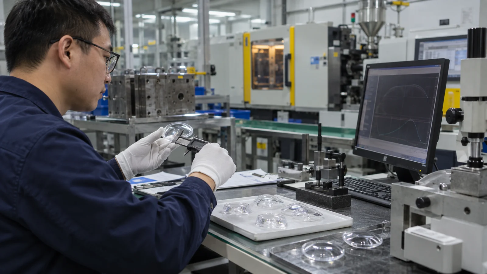
An instrument displaying additional decimal places is not automatically capable of accepting a tight tolerance. Fixture repeatability, edge detection, temperature, operator setup and data filtering all contribute uncertainty. Run repeatability and reproducibility work on representative transparent parts, because clear edges can behave differently from calibration artifacts.
Freeze the acceptance method with the drawing
State whether surface form is evaluated over the full aperture or after removing tilt and power, whether the part is free or constrained, and how outliers are treated. If buyer and supplier use different filters or fixtures, both can follow the drawing and still disagree. A shared method and correlated samples should be approved before production tooling is released.
Review tolerance changes as system changes
Tightening one molded dimension can shift cost into tool correction, cycle time, inspection and yield without improving the assembly. Before revising a limit, rerun the optical sensitivity and stack analysis. Sometimes a locating feature, compliant mount or calibration step controls output more effectively than a tighter lens dimension.
For procurement, request the proposed measurement method and capability by cavity rather than a generic promise of “high precision.” Ask which dimensions are controlled in the mold, which require process compensation, and which optical characteristics are verified functionally. This creates comparable quotations and exposes assumptions early.
Frequently Asked Questions
Can standard molded-part tolerances be used for lenses?
They can guide nonoptical features, but optical surfaces and axis relationships need function-specific limits and measurement methods.
Should the CAD nominal equal the tool surface?
Not necessarily. Predictable molding shrinkage and form change may require compensated steel after stable trial data is available.
How should suppliers quote a tight optical tolerance?
They need the drawing, optical function, material grade, measurement definition, sample plan, assembly condition and acceptance data—not the tolerance value alone.