
The gas assist molding process can produce a light, hollow section without the sink marks expected from a solid thick wall. But a neat short shot alone does not make the cycle stable. Resin fill, gas delay, pressure hold, cooling and venting must leave the gas a predictable route through the still-molten core. If one stage shifts, the part may fill yet have a short gas channel, a surface mark or an unexpectedly thin wall.
This is a process-window guide for engineers reviewing a trial, not a general list of benefits. For the service scope and part types, see страница о литье под давлением с газовым ассистированием. Here the question is narrower: what should a team measure before it changes the gas settings?
В этой статье
- The shot sets up the route
- The delay changes the melt core
- The hold must reach the thick section
- Read the part before changing a setting
- What to preserve for production
- Questions from a process review
The Shot Sets Up the Route; It Does Not Finish the Fill
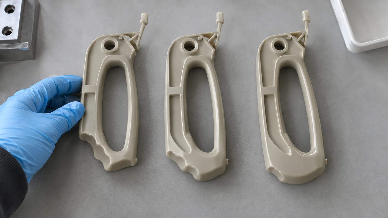
In a short-shot cycle, resin first occupies part of the cavity. Nitrogen then displaces the hot core of a deliberately thick section and can push molten resin toward the end of flow. The outer skin has already begun cooling against the mold. That difference between a cooler skin and a mobile core is what makes a controlled hollow path possible.
A shot that is too small can leave too little melt ahead of the gas, increasing the chance of incomplete filling or gas breakthrough. A shot that is too large may leave insufficient room for useful penetration. There is no universal percentage that can be transferred from one part to another: gate position, resin, channel geometry and wall thickness change the usable range. Record the actual shot setting and molded part weight during trials, then section representative parts to see where the gas went.
Do not treat every dark or hollow-looking feature as proof of a complete channel. A cut section can reveal a solid segment behind an otherwise acceptable exterior. That segment can continue to cool and shrink differently from the intended hollow area.
The Gas Delay Changes Which Core Is Still Movable
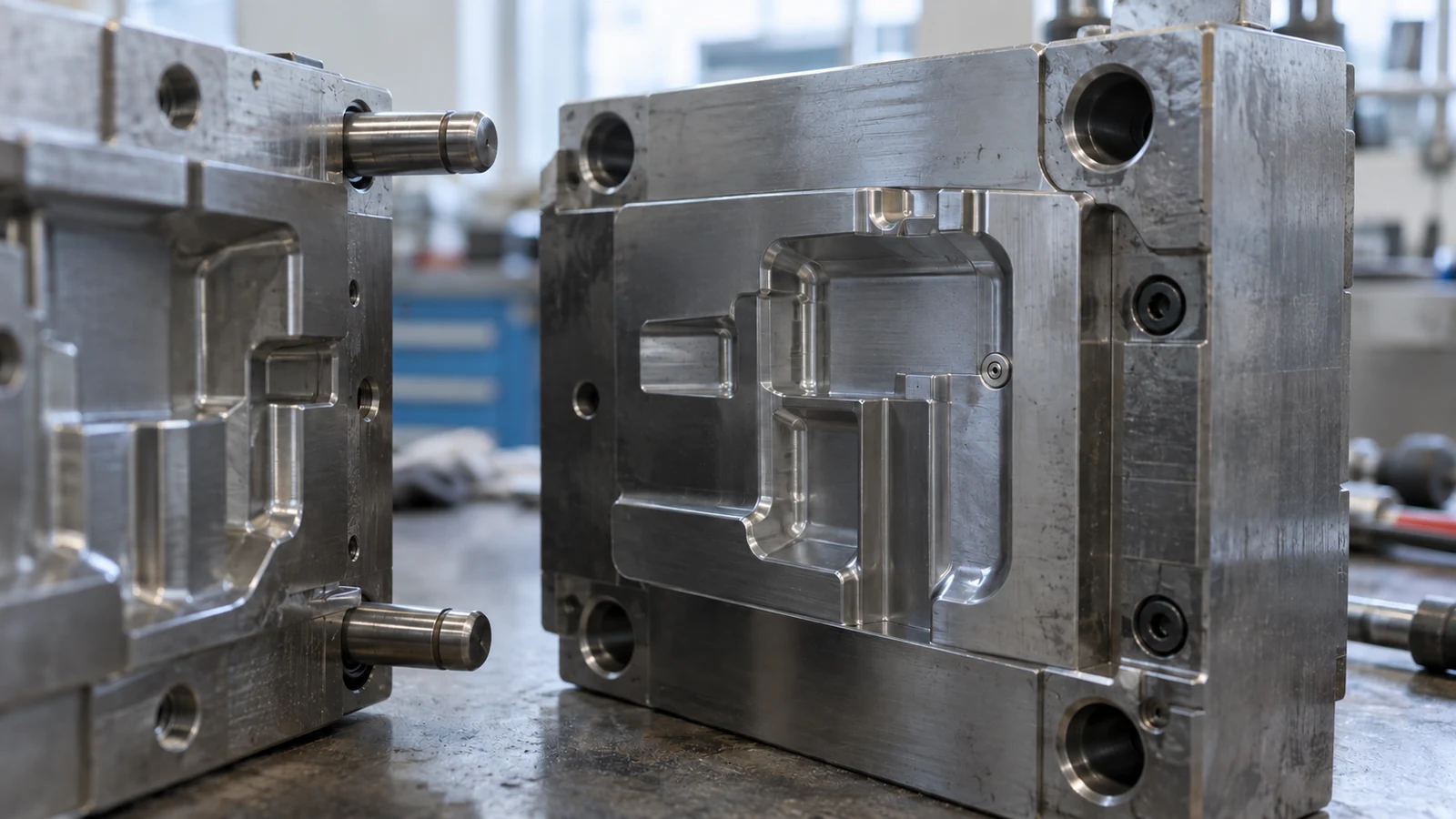
The interval between resin filling and gas entry determines how much of the core remains mobile. If gas enters before a useful skin has formed, it may wander into a thin wall or break through the surface. If it enters after the thick route has frozen too far, penetration can stop early and leave a sink-prone mass near the end of the channel.
Delay cannot be judged in isolation. Melt temperature, mold temperature, shot size and local wall thickness all affect cooling. Change one variable at a time during a controlled trial and compare section cuts at the same locations. A visible surface improvement is useful evidence, but it does not show whether the hollow section is continuous or whether the remaining wall is adequate for the part’s load.
If a process only works at one narrow combination of settings, inspect the geometry as well as the recipe. Gas tends to follow the hotter, thicker route of lower resistance. A poor route cannot always be repaired by raising pressure.
The Hold Must Reach the Thick Section That Is Shrinking
Gas pressure can support the surface from inside while the resin cools, but it only helps where a connected gas path actually reaches. A thick rib left solid beyond a stopped channel can still show sink or differential shrinkage. The pressure profile and hold time therefore need to be judged alongside gas penetration and cooling, rather than used as stand-alone quality indicators.
Increasing pressure is not a safe default response to every defect. It can move the gas front into an unintended region or thin the wall near a corner. First identify whether the problem is short penetration, an unstable front, insufficient packing of a specific surface, or uneven cooling. If the issue originates in the planned flow path, a анализа литьевых процессов can help test the relationship among fill pattern, gas route and geometry before another tooling change is approved.
Read the Part Before Changing the Settings
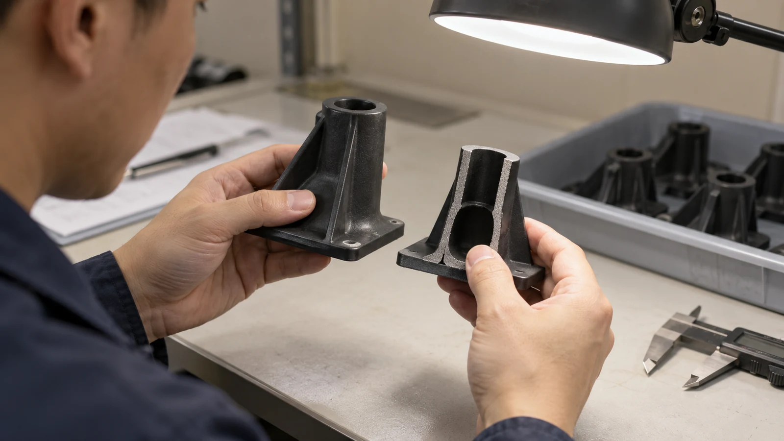
A process trial is easier to interpret when each symptom is paired with physical evidence. Compare parts made under identified settings, and keep the cut plane, measurement locations and appearance criteria consistent. The table below describes a diagnostic starting point, not a guaranteed cause.
| Observation | Check first | Evidence to retain |
|---|---|---|
| Sink remains near a thick end | Whether the hollow path reaches that section | Section cut and surface photograph |
| Gas breaks through a wall | Remaining melt ahead of gas, timing and local wall geometry | Breakthrough location and shot record |
| Hollow length varies by cycle | Shot consistency, gas entry and thermal stability | Part weights and repeated section cuts |
Process changes should be judged against the drawing’s critical surfaces and dimensions, not against part weight alone. A lighter part is not automatically a better part if wall continuity, stiffness or surface quality becomes less predictable.
What to Preserve When the Trial Becomes Production
Approval should define both the machine-side window and the part-side evidence. Preserve the resin identification, shot setting, gas entry timing, pressure profile, hold and vent sequence, mold temperature conditions, and an agreed method for checking the hollow section. Record which dimensions and visible surfaces matter to the buyer. These are items to review for a specific project, not a claim that one universal window exists.
- Mark the section planes. Select locations that reveal the start, bend and end of the intended gas path.
- Agree on pass conditions. State the required appearance, wall continuity and drawing dimensions before judging samples.
- Keep a change record. If a parameter moves, compare the new part against the same section and inspection plan.
For a design still before tooling, it is better to review the intended gas route alongside the part drawing than to rely on a process trial to discover a missing channel.
Questions from a Process Review
Can more gas pressure cure a short hollow channel?
Not reliably. First establish whether the melt route has frozen, the gas entry is misplaced or the channel geometry is ambiguous. More pressure can create a new thin-wall defect without extending the desired path.
Is a good-looking exterior enough to approve the cycle?
No. Appearance should be paired with section checks and the dimensions or mechanical requirements on the drawing. The unseen hollow path is part of the functional result.
Which files help assess a difficult trial?
Provide the 3D model, drawing, resin grade, marked appearance faces, expected load direction and photographs or section cuts of the defect. Those details make a process review much more specific than a list of machine settings.