
Designing metal-plastic hybrid assemblies requires balancing the dimensional variations of pre-formed metal components against the volumetric shrinkage of molten thermoplastics. Metallic inserts stamped or turned on high-speed equipment inevitably exhibit tolerance stack-up, varying slightly in thickness, knurl outer diameter, or contact pad straightness.
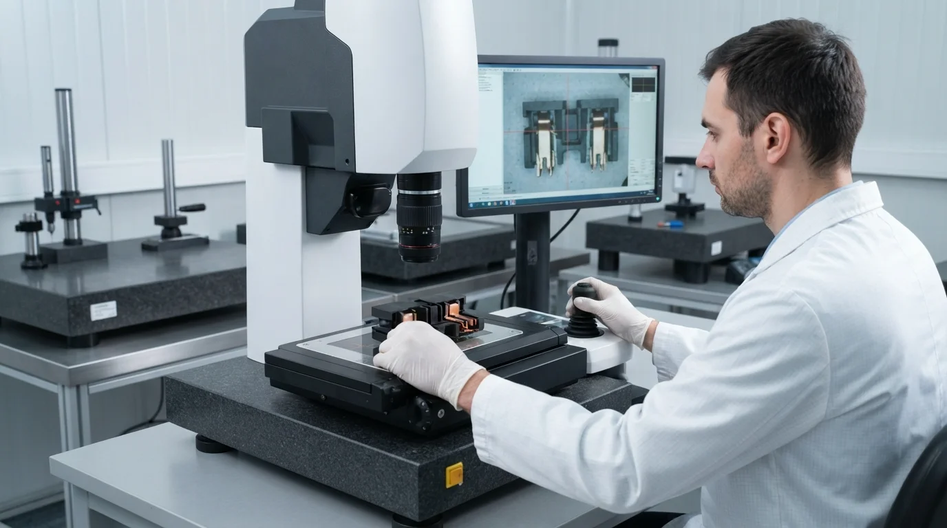
Injecting high-viscosity resin into mold cavities under elevated clamping pressure forces plastic into any micro-gaps existing between the tool steel and the metal substrate. Sub-millimeter gap variations can permit molten resin to bleed over active electrical contacts, causing high scrap rates and costly manual deflashing. This technical engineering guide analyzes interfacial shut-off mechanics, core locating pin design, thermal expansion differentials, and metrology verification standards.
Inhaltsverzeichnis
Managing Metal-Plastic Interfacial Tolerances & Shut-off Precision (±0.01 mm)
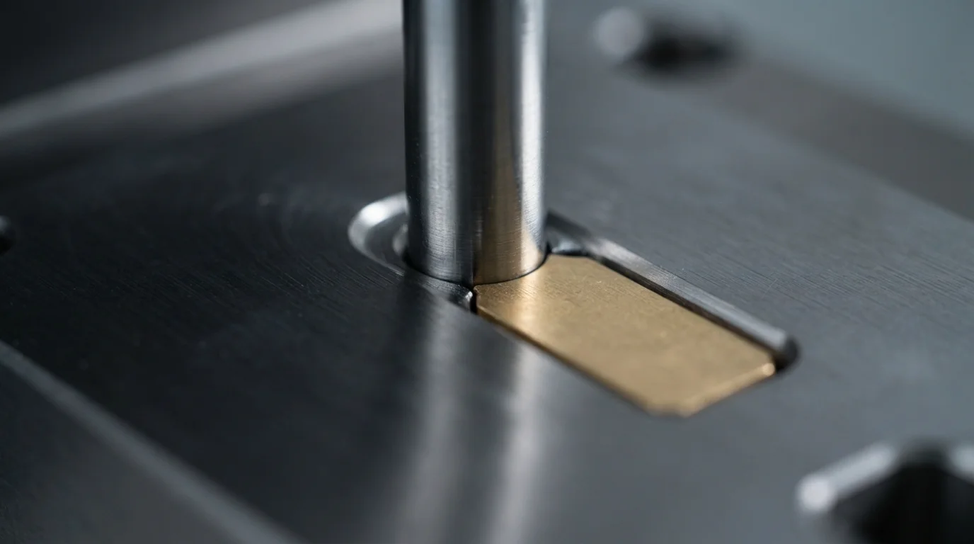
Controlling insert molding tolerances along the metal-to-plastic boundary dictates whether the finished assembly functions cleanly without cosmetic flash. Precision toolmakers design shut-off steel lands with fitment tolerances maintained under ±0.01 mm, creating a tight physical seal against embedded Messing oder Kupfer contacts. Achieving tight shut-off lands prevents low-viscosity resin from bleeding onto active electrical contact faces during high-pressure packing.
Dimensional drift in pre-stamped metal inserts presents a continuous challenge for shut-off land fitting. Oversized metal inserts crush cavity steel upon clamp-up, causing permanent mold damage and premature tool wear. Conversely, undersized inserts leave microscopic clearances that allow plastic to bleed, requiring spring-loaded floating core shut-offs that adapt dynamically to minor metal thickness variations.
Minimizing Insert Displacement During High-Pressure Injection

Die Verhinderung der Einsatzbewegung während der Formkavitätsfüllung erfordert robuste mechanische Rückhaltefunktionen, die direkt in den Formkern integriert sind. Hochgeschwindigkeits-Schmelzfronten üben erhebliche hydrodynamische Kräfte aus, die unverankerte elektronische Stifte biegen oder Gewindebolzen kippen können. Die Integration von gehärteten Positionierstifte, Kernmagneten oder pneumatischen Spannschiebern hält den Metalleinsatz während der Hochdruckinjektion fest gegen den Formstahl.
Die Optimierung der Einspritzdruckprofile schützt empfindliche Metalleinsätze vor physikalischen Scherkräften. Die Implementierung mehrstufiger Füllprofile ermöglicht es der Schmelzfront, den Einsatz sanft zu umhüllen, bevor der endgültige Nachdruck aufgebracht wird. Die Einhaltung strenger Dimensionsparameter während Umspritzen stellt sicher, dass interne Komponenten eine präzise räumliche Ausrichtung im Kunststoffgehäuse beibehalten.
Thermische Ausdehnungsdifferenzen & elastische Dehnung in Metall-Kunststoff-Verbindungen
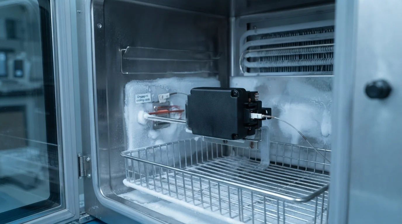
Die Verwaltung des Unterschieds im Wärmeausdehnungskoeffizienten (CTE) zwischen starren Metallen und umgebenden Polymeren verhindert Spannungsrisse nach dem Formen. Metalle dehnen sich mit 16,5 bis 18,5 ppm/K aus und ziehen sich zusammen, während technische Harze beim Abkühlen mit deutlich höheren Raten schrumpfen. Thermische Kontraktionsunterschiede induzieren lokale Umfangsspannungen in der Kunststoffwand, die den Metalleinsatz umgibt.
Die Auswahl von Harzen mit hoher Dehnung wie PA66, PBT, oder PC/ABS absorbiert elastische Dehnung, ohne Mikrorisse zu entwickeln. Das Vorheizen von Metalleinsätzen auf 100 °C vor dem Formen reduziert anfängliche Temperaturgradienten und fördert eine gleichmäßige Polymerabkühlung. Ein korrekter thermischer Abgleich gewährleistet Dimensionsstabilität über erweiterte Temperaturwechselprüfungen.
| Werkzeugtoleranzparameter | Standard-Formklasse | Präzisions-Einsatzwerkzeug | Primäre technische Fehlervermeidung |
|---|---|---|---|
| Sperrkanten-Passung | ±0,05 mm | ±0,01 mm | Eliminates polymer resin bleed over electrical contact pads |
| Locating Pin Concentricity | ±0.03 mm | ±0.005 mm | Prevents insert tilt & displacement during high-velocity melt fill |
| Insert Outer Diameter Tolerance | ±0.08 mm | ±0,02 mm | Prevents steel cavity crushing and Parting Line wear |
Metrology Validation: Zeiss CMM (±0.003 mm) and FAI Quality Reports
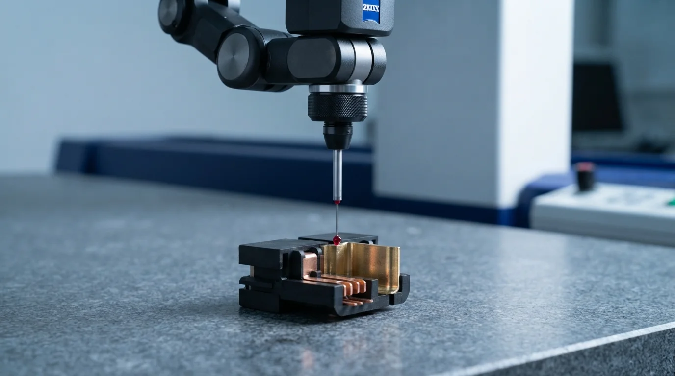
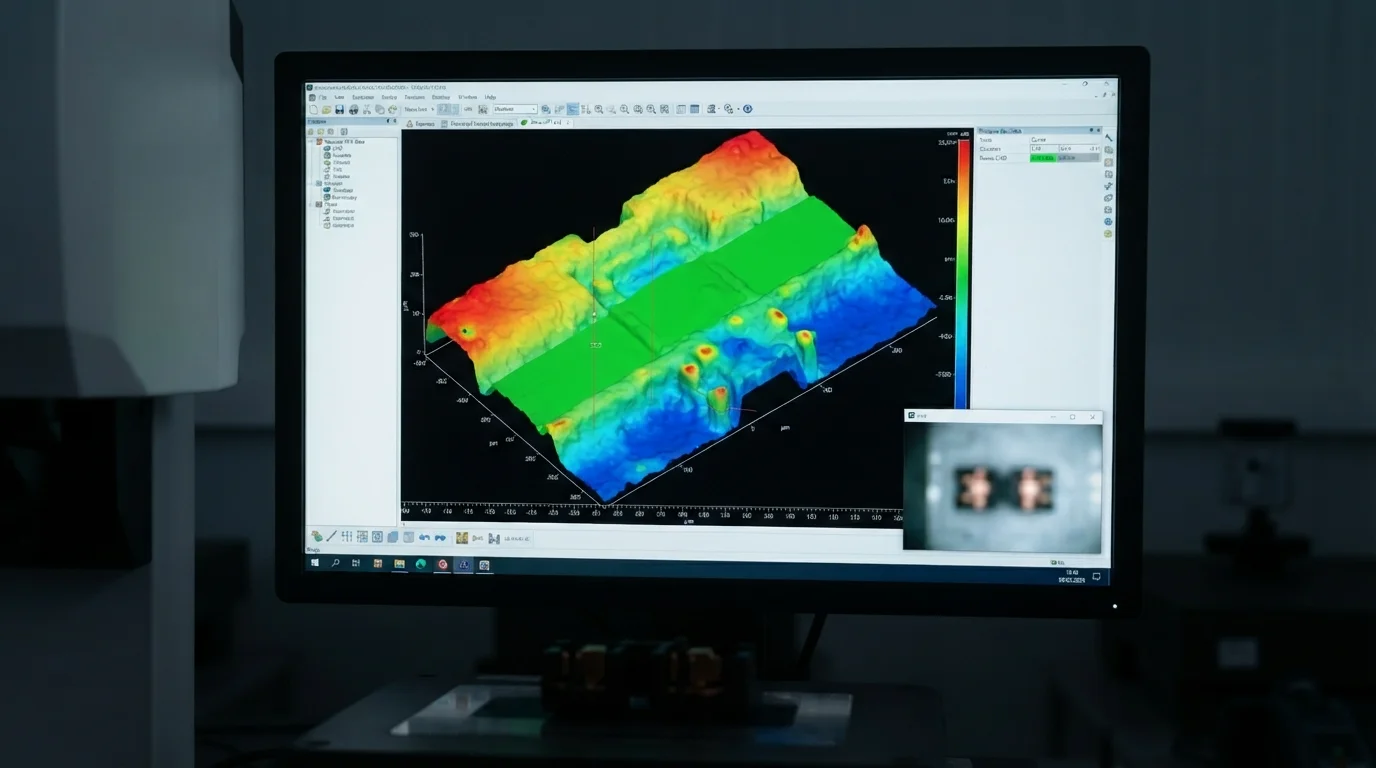
Verifying true position tolerances on encapsulated metal components requires advanced metrology instrumentation inside climate-controlled testing laboratories. Quality control technicians utilize automated Zeiss CMM coordinate measuring machines with a scanning precision of ±0.003 mm to scan critical dimensions. Measuring true position concentricity, hole pitch, and shut-off line flatness guarantees assembly alignment.
Comprehensive First Article Inspection (FAI) reports document critical-to-quality dimensions across initial T1 production samples. Quality assurance systems conforming to IATF 16949 and ISO 13485 verify raw material Certificates of Analysis (COA) for every shipment. Establishing statistical process control protocols with CpK > 1.67 ensures consistent batch-to-batch tolerance repeatability across high-volume production runs.
Häufig gestellte Fragen (FAQs)
Why do metal insert dimensional variations cause plastic flash in insert molding?
Metal inserts manufactured with wide stamping tolerances vary in thickness from piece to piece. Undersized inserts leave micro-gaps between the metal surface and mold shut-off steel, permitting molten plastic to bleed over active contact pads. Utilizing spring-loaded floating tool shut-offs compensates for insert thickness variations, preventing flash.
How do locating pins prevent insert displacement during high-pressure injection?
Locating pins physically lock the metal insert into the mold core, preventing hydrodynamic melt forces from tilting or shifting the insert during filling. Precision locating pins fit internal pilot holes or threaded bores tightly, maintaining sub-millimeter axial alignment throughout the injection cycle.
What metrology equipment is best for measuring insert molding tolerances?
Automated 3D coordinate measuring machines (CMM) and non-contact optical measuring profilers deliver the highest metrology accuracy. Optical profilers scan delicate contact pins without physical deflection, while 3D CMMs verify true position concentricity down to ±0.003 mm.