
Micro overmolding adds a second material around a tiny plastic, metal, electronic, or elastomeric element. Its value comes from combining functions such as sealing, insulation, grip, strain relief, or component retention in a small package. Its risk sits at the interface: the first component can shift, deform, contaminate, flash, or bond unpredictably during the second shot.
A sound design treats the interface as a functional feature. Retention, material compatibility, shutoff, heat and pressure exposure, ejection, and inspection must be developed together.
Interface review
The Interface Is the Product
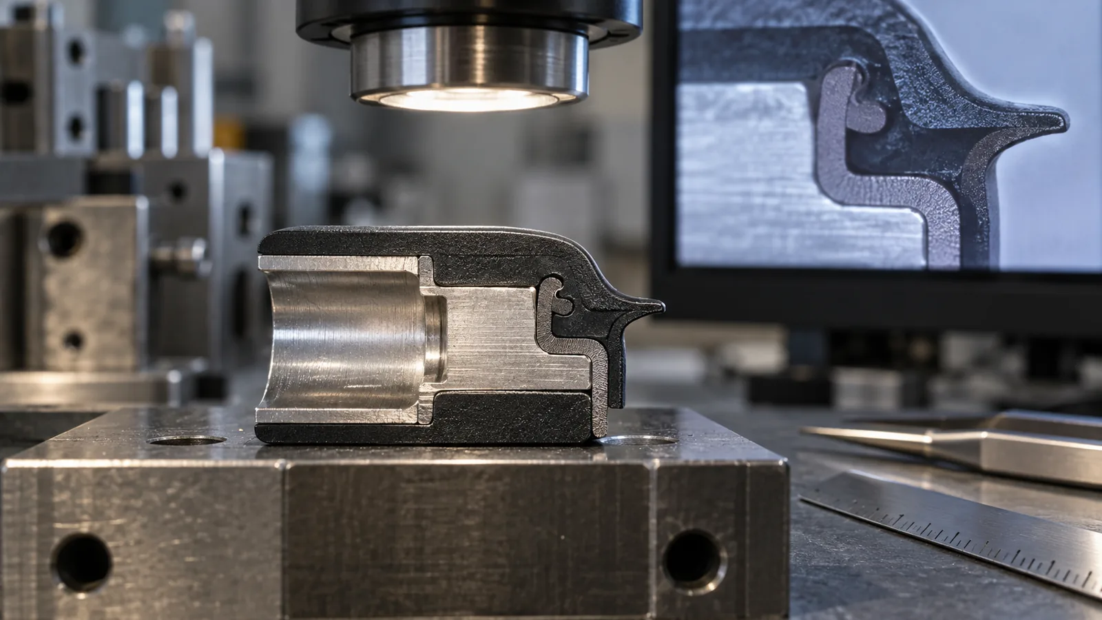
State what the interface must do: carry pull load, resist peel, seal pressure, block moisture, provide electrical insulation, prevent rotation, transfer torque, or survive repeated flexing. Each function creates a different failure mode and test.
Then mark the interface geometry on the drawing. Bonded area, mechanical interlock, edge distance, shutoff, allowed flash, and any no-contact surface should be explicit. A broad statement such as “good adhesion” cannot guide tool design or acceptance.
The loading direction matters. A bond that resists shear may remain vulnerable to peel at a thin edge. Mechanical keys can improve retention but also trap gas, create knit lines, or weaken the first component. Qualification should reproduce the real direction and rate of load.
Decide What Holds the First Component in Place
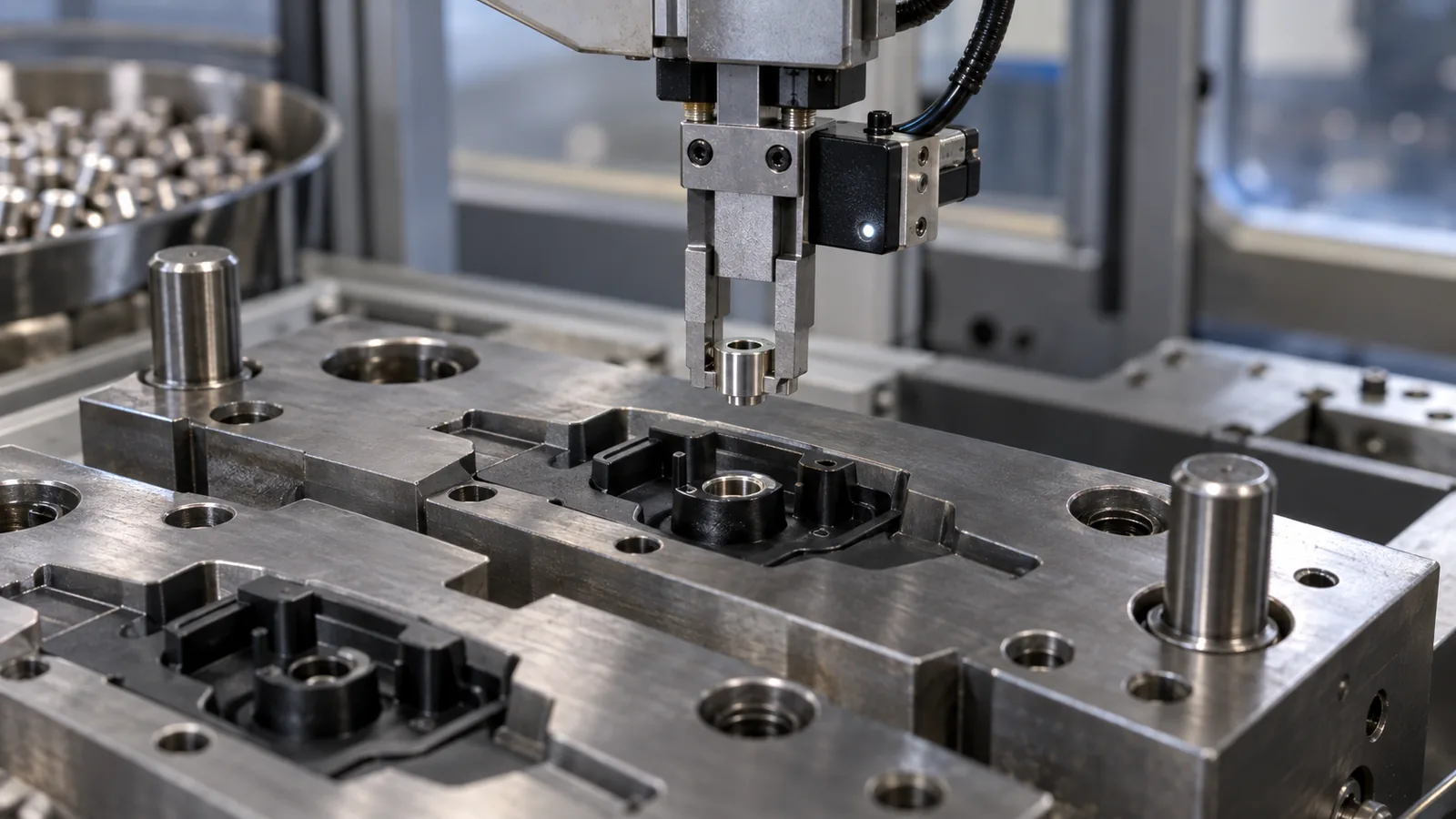
The first component must remain located while the mold closes and melt enters. Locating pins, nests, vacuum, mechanical features, magnetic support for suitable metals, or automated end-of-arm tooling may be used. The chosen surfaces become part of the dimensional stack and can leave witness marks.
Small inserts are sensitive to static, orientation, and contamination. Feeding and placement should include presence detection and, where needed, orientation verification. A sensor that only sees “an object” may not distinguish an upside-down or partially seated insert.
Review tolerance between the insert and locating nest. Too much clearance permits shift or flash. Excessive interference can damage the insert or prevent full seating. The insert injection molding process provides relevant locating and retention principles when the first component is metal or another prefabricated part.
Material Compatibility Is More Than Adhesion
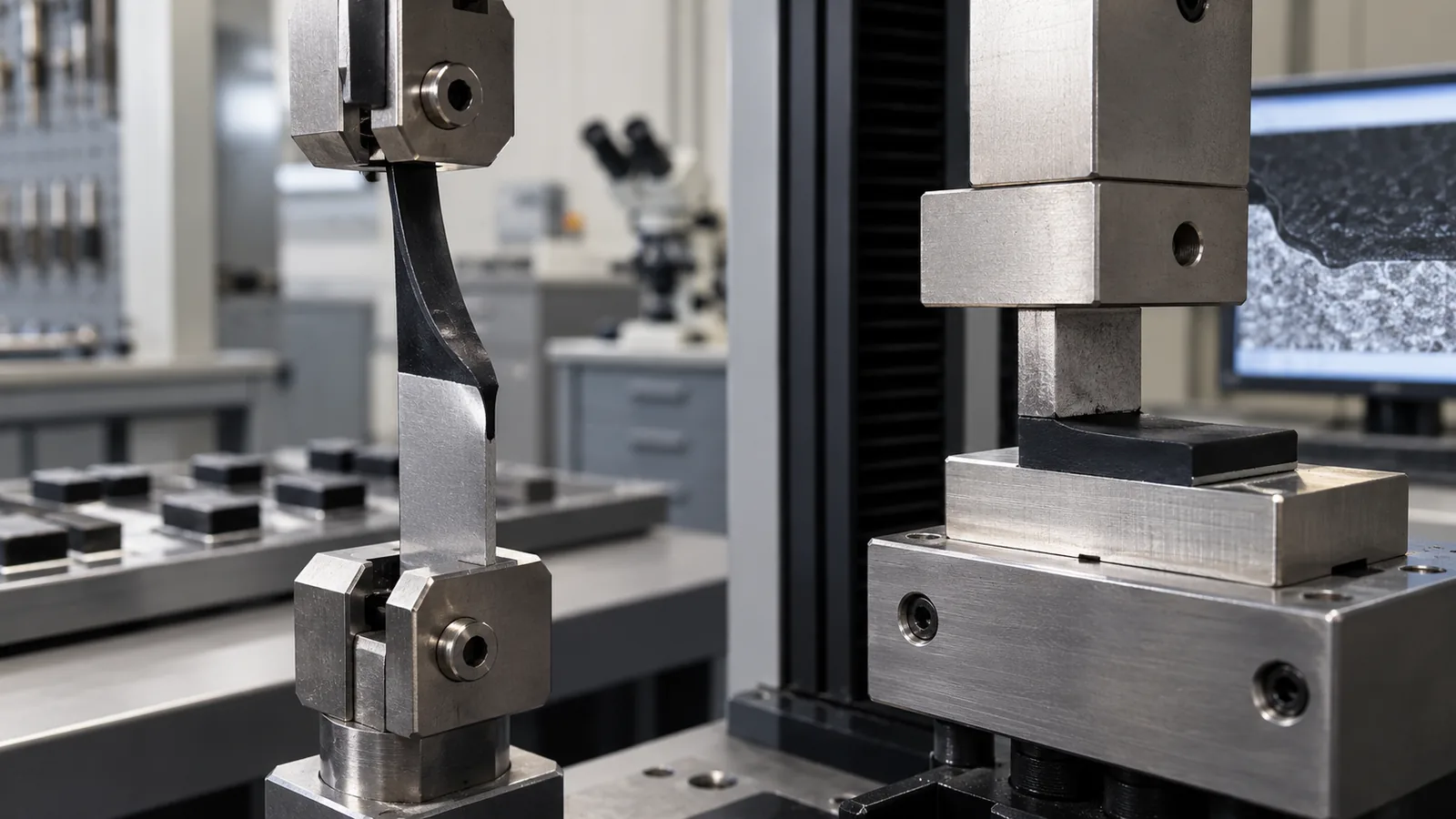
Chemical compatibility is important, but surface condition, melt temperature, insert temperature, contact pressure, time, colorant, additives, moisture, and aging can alter bond performance. A published compatibility chart is a screening tool, not production approval.
| Interface strategy | Strength | Risk to validate |
|---|---|---|
| Chemical bonding | Clean geometry and continuous seal potential | Grade, surface, temperature and aging sensitivity |
| Mechanical interlock | Less dependent on polymer affinity | Gas traps, thin sections and stress concentration |
| Surface treatment or primer | Can improve difficult interfaces | Coverage, cleanliness, shelf life and process control |
Use the actual resin grades, colorants, and insert condition in testing. For soft-touch or sealing layers, the thermoplastic elastomer family page can support early screening, followed by grade-specific trials.
Control Flash Around a Miniature Boundary
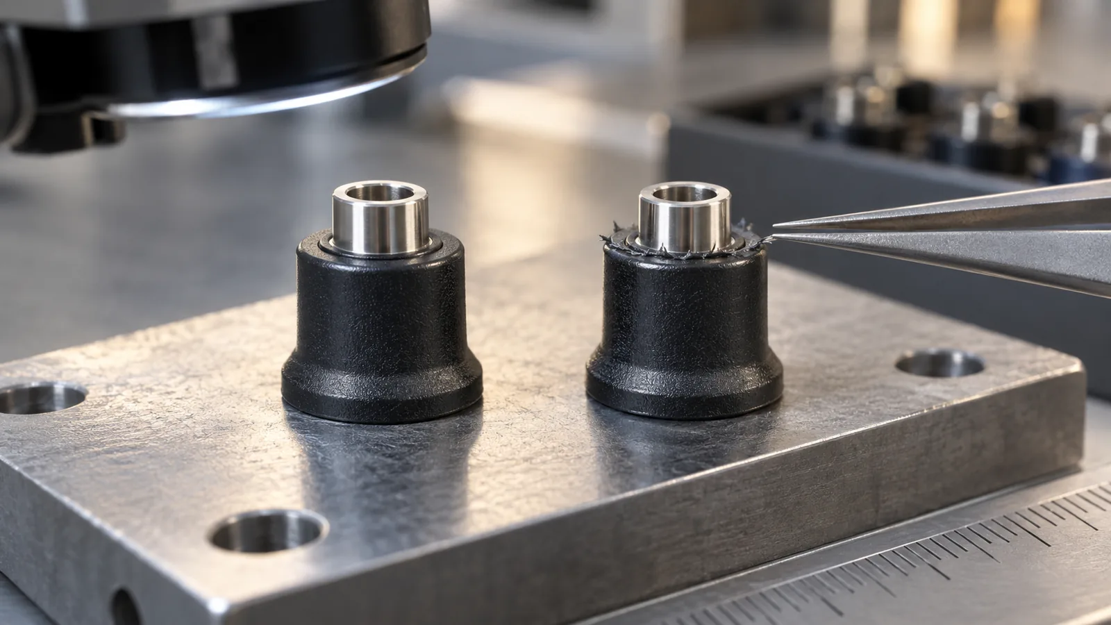
The shutoff must seal against the first component without crushing or marking it. Insert tolerance, seating variation, mold alignment, thermal expansion, surface debris, and cavity pressure all affect the boundary. A small mismatch can create flash that interferes with sealing or assembly.
Define where steel closes on steel and where it closes on the insert. Flexible or dimensionally variable inserts may require a compliant strategy, but compliance can also permit movement. Tool contact should be checked across the full insert tolerance and after expected wear.
Venting is especially important near an enclosed interface. Trapped air can prevent the second material from reaching an edge or can be compressed into a burn mark. The vent path must remain open until the flow front arrives without becoming a flash path.
Protect Inserts During the Second Shot
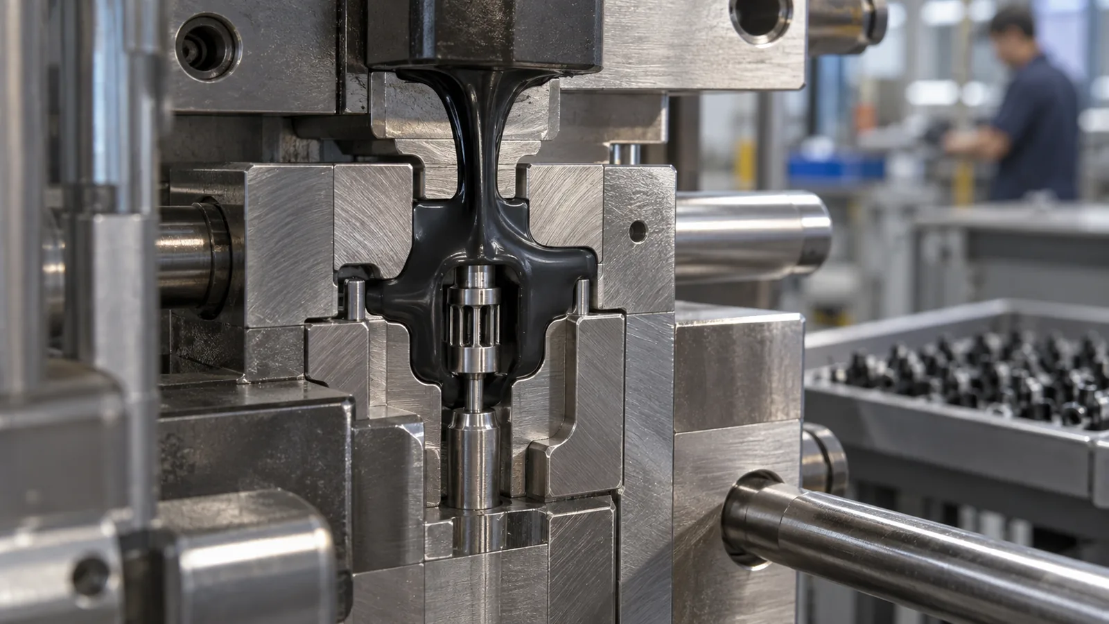
The second shot applies heat, pressure, and shear. Thin plastic substrates may soften or distort. Wires, contacts, membranes, and microfeatures can move. Sensitive electronics may face temperature, pressure, or moisture limitations.
Gate location should direct force into supported areas and avoid jetting across a delicate element. Filling profiles can be staged, but an extreme process used to protect one feature may leave another incomplete. Support geometry, venting, material temperature, and injection sequence should create a workable window.
- Measure the first component and seating position.
- Verify presence and orientation before mold close.
- Record gate-facing deformation and interface fill.
- Inspect hidden areas with sectioning or suitable imaging.
- Test electrical, sealing, or mechanical function after molding.
- Repeat after environmental conditioning and aging.
Inspect Bonding Without Hiding Dimensional Error
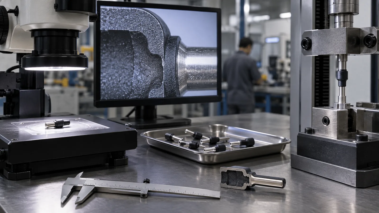
A pull test can demonstrate retention while missing a shifted insert, thin seal, or local flash. Visual inspection can find boundary defects but cannot quantify adhesion. Use complementary methods tied to the failure modes.
Dimensional inspection should reference the finished assembly datum. Cross-sections can reveal overmold thickness, voids, wetting, and insert location. Leak, peel, torque, electrical, or flex tests should reproduce the use direction and environment.
The main overmolding process page covers broader multi-material capability. For a micro-scale project, the Micro Injection Molding controls for small-shot delivery, precise tool location, gentle handling, and feature-level metrology remain equally important.
Keep test results traceable to insert lot, cavity, material lot, placement system, and cycle sequence. That record is often the fastest way to distinguish a bonding drift from a dimensional seating problem.
Frequently Asked Questions
Does compatible material chemistry guarantee a bond?
No. Surface condition, temperature, pressure history, additives, moisture, geometry, and aging can change performance. Test the actual production pair.
When is a mechanical interlock useful?
It is useful when chemical adhesion is weak or extra retention is needed, provided the interlock can fill, vent, and release without weakening the components.
Why does flash appear only around some inserts?
Insert dimensional variation, incomplete seating, contamination, local shutoff wear, or placement error can change the boundary from cycle to cycle.
Should bond strength be tested immediately?
Immediate testing is useful, but qualification should also include the conditioning, aging, chemical, temperature, or flex exposure expected in service.
What belongs in a micro-overmolding RFQ?
Include both component drawings, exact materials, interface function, load direction, insert tolerances, allowed witness zones, environmental tests, automation needs, and annual volume.