
High-voltage distribution in electric vehicle (EV) battery systems requires robust, insulated pathways to connect modular cell stacks safely. Traditional wiring harnesses are bulky, labor-intensive to assemble, and prone to routing errors under high-vibration conditions. Integrating conductive copper or aluminum conductors directly into structural plastic enclosure elements solves these issues while maximizing spatial efficiency. This technical engineering guide addresses the tooling configurations, material science selection criteria, and quality validation processes essential for metal-plastic overmolding.
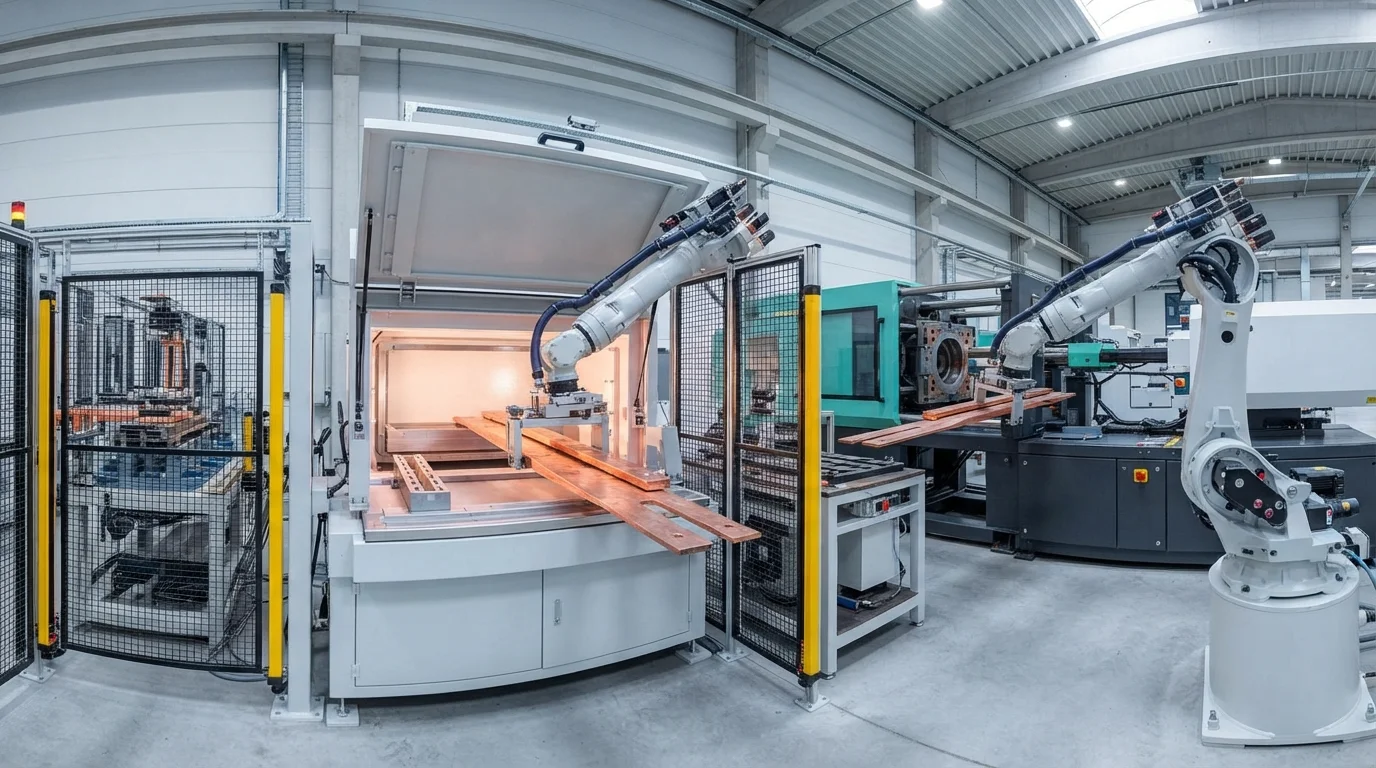
Table of Contents
Solving Thermal Expansion Mismatch in Metal-Plastic Overmolding
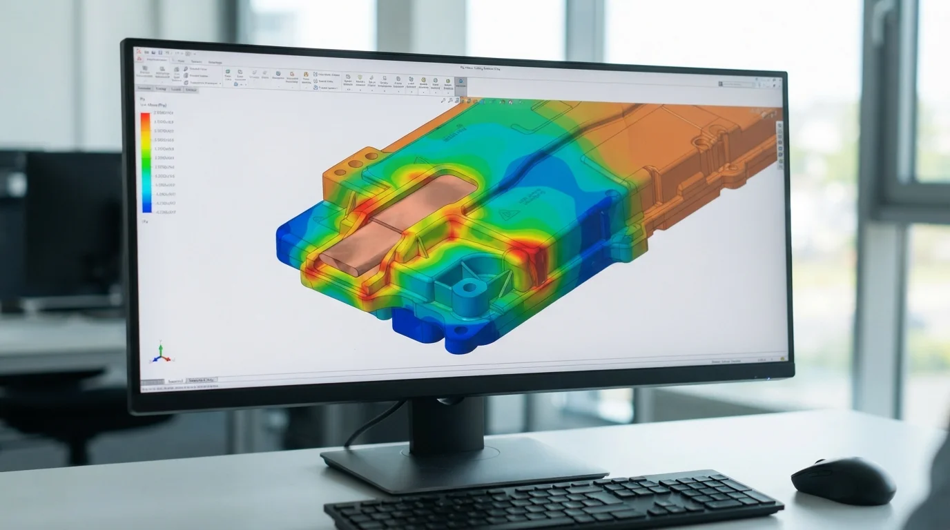
Integrating copper or aluminum busbars directly into the plastic structure simplifies assembly, and performing insert molding busbars in EV battery covers provides a robust insulation layer that prevents short circuits. However, fusing rigid metal and molten thermoplastic introduces severe physical stress because of the vast difference in their coefficients of thermal expansion (CTE). Copper expands at approximately 16.5 ppm/K, whereas typical engineering resins shrink and expand at significantly higher rates. During the cooling phase of the injection cycle, this thermal mismatch causes localized residual stress inside the polymer, potentially leading to micro-cracking around the metallic insert.
To neutralize this mechanical stress, our tooling engineers implement a structured approach:
- Preheating metal inserts—Warming the copper terminals to 100°C before loading them into the mold core reduces localized thermal shock during polymer injection.
- Optimizing melt holding pressure—Applying multi-stage holding profiles prevents packing stresses from concentrating near the metal-to-plastic boundaries.
- Selecting high-elongation resins—Using custom impact-modified polyamides or custom PBT blends increases physical resilience around sharp metal corners.
- Integrating rounded insert corners—Rounding the edges of the metallic busbars prevents physical stress-riser points from shearing the surrounding plastic.
Preventing high-voltage clearance failures when executing insert molding busbars in EV battery covers relies on these critical prep steps. Our tool shop custom-grinds every metal shut-off face to guarantee airtight encapsulation. Proper preparation guarantees that parts survive extensive automotive thermal shock cycle testing without physical degradation.
Ensuring High-Voltage Creepage and Clearance Compliance
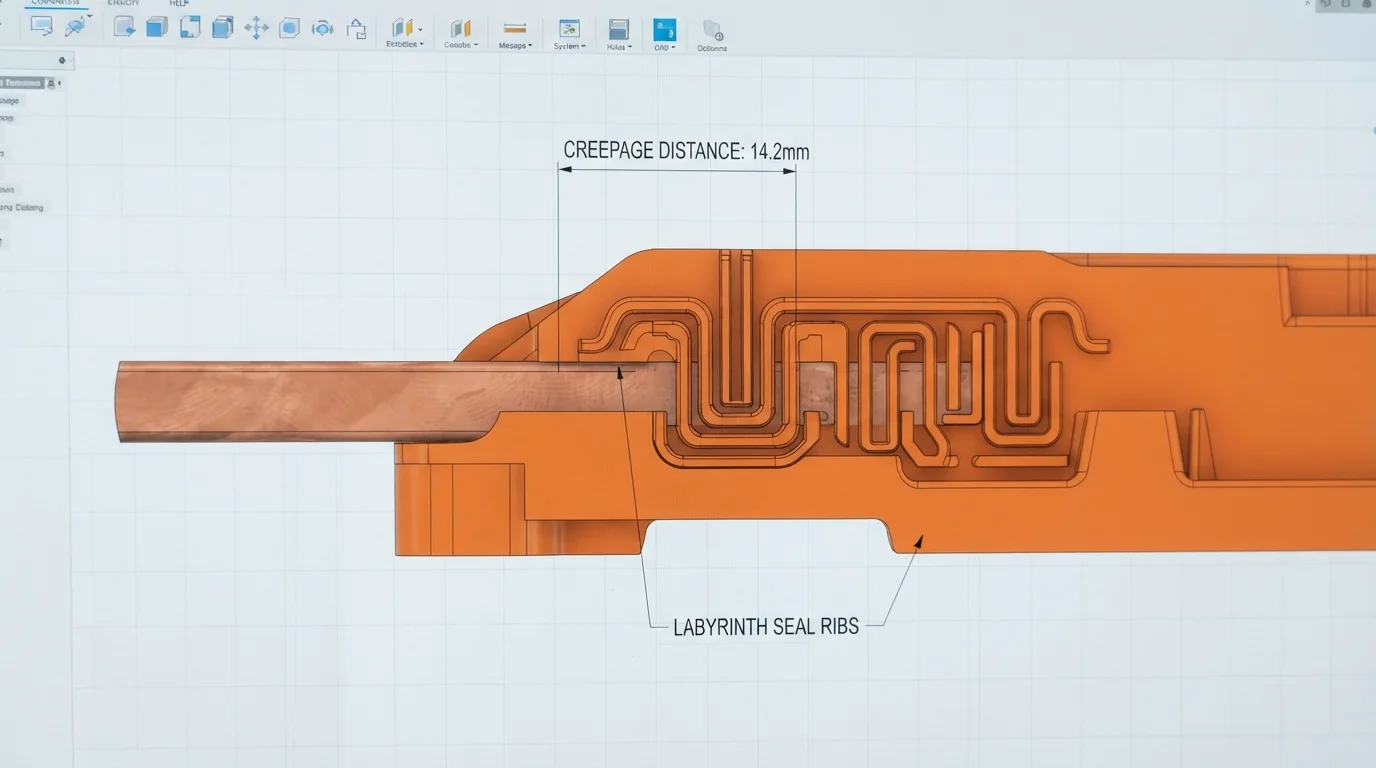
Ensuring strict high-voltage safety compliance is mandatory as automotive platforms transition from 400V to 800V architectures. Designing direct plastic-metal interfaces requires strict adherence to international electrical insulation standards like IEC 60664-1. Moisture, salt spray, and atmospheric particulate deposits can create conductive tracking paths along the boundary where plastic meets metal. To combat tracking failures, tooling designers incorporate elevated labyrinth ribs along the perimeter of the exposed metal contacts.
These raised polymer barriers artificially extend the physical creepage distance without increasing the overall footprint of the battery pack cover. Controlling differential shrinkage of the polymer matrix during insert molding busbars in EV battery covers prevents the formation of micro-gaps along these labyrinth boundaries. Even a 0.05mm gap can collect moisture, facilitating high-voltage leakage or catastrophic dielectric breakdown. We utilize multi-point injection gates to balance cavity filling, securing a tight physical seal along every square millimeter of the metal substrate.
Ultimately, our proven capability for insert molding busbars in EV battery covers is a key capability for manufacturing advanced custom plastic battery housings for EV. This structural consolidation shaves weight while simplifying automated final pack assembly lines. Incorporating insulated busbars directly into your enclosure components eliminates loose wires, enhancing assembly reliability for demanding heavy-duty platforms.
Frequently Asked Questions (FAQ)
How do you prevent plastic flash from forming on active busbar contact pads?
Preventing plastic flash requires maintaining tooling shut-off tolerances below 0.015mm. Our tooling designers utilize spring-loaded floating inserts inside the mold core to compensate for variations in copper sheet metal thickness. This dynamic pressure clamping ensures a tight seal against the active connection terminals during high-pressure injection.
What insulating resins are best for 800V busbar encapsulation?
Polyamide 66 with 30% glass fiber (PA66-GF30) or polybutylene terephthalate (PBT) are the primary engineering choices. These polymers offer exceptional comparative tracking index (CTI) ratings of over 600V while providing the mechanical stiffness needed to resist dynamic vibration loads.
How do you test the seal integrity of overmolded busbars?
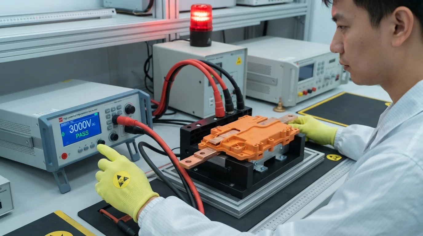
Quality verification utilizes high-pressure bubble leak testing and high-potential (Hi-Pot) electrical isolation testing. Applying 3,000V DC across the encapsulated copper confirms zero dielectric insulation leakage under simulation conditions.