
Low-pressure molding defects are easiest to diagnose when the encapsulated assembly is inspected as an interface system. A gap, flash edge, shifted wire, incomplete coverage, or weak bond can involve material flow, trapped air, assembly location, substrate condition, shutoff design, or handling. Record where the defect occurs and whether it repeats on the same feature before changing material or process settings.
Classify the failure before adjusting the process
First identify which requirement failed: coverage, boundary, adhesion, component position, electrical function, or environmental protection. Photograph and retain a representative part, note the assembly revision and material lot, and mark the defect location. The same visual symptom can have different causes depending on whether it appears at a cable exit, a connector face, a thin wall, or an interface between two substrates.
Compare the defect across samples. A repeated defect at one tool location suggests a local cavity or assembly-position condition; a change affecting many parts after a material lot, setup, or handling change suggests a broader variable. These are clues, not proof. Confirm with inspection and process records.
Đọc các mẫu lỗi phổ biến
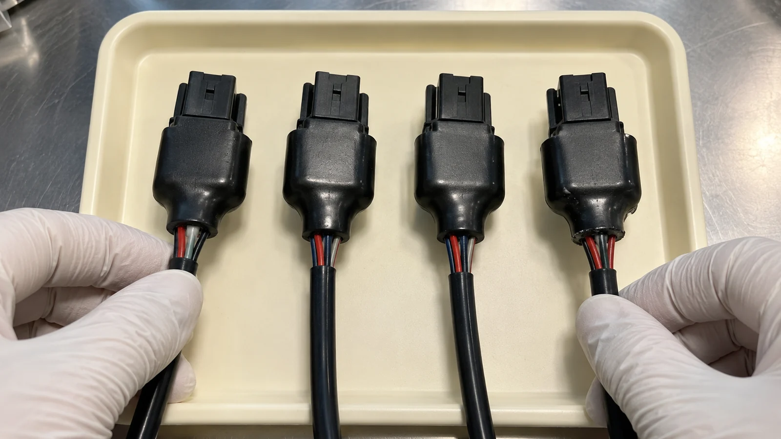
| Observed issue | Kiểm tra đầu tiên | Không giả định |
|---|---|---|
| Incomplete encapsulation or a visible gap | Flow path, gate, venting, assembly position, and material condition | That higher pressure is safe for the electronics. |
| Flash or material on a keep-out surface | Shutoff fit, cable location, parting line, and assembly variation | That trimming is an acceptable permanent correction. |
| Wire or component shifts after molding | Fixture support, flow direction, loading repeatability, and cavity clearance | That low-pressure molding eliminates all assembly forces. |
| Bond or seal fails in service | Substrate identity, surface condition, grade compatibility, and validation exposure | That a visual bond on one sample proves long-term adhesion. |
| Voids or trapped air | Fill sequence, vent path, assembly geometry, and material flow behavior | That the material alone is at fault. |
This matrix is a triage aid. Confirm the suspected cause with representative assemblies and the approved acceptance criteria; do not use a single symptom to justify a tool or material change.
Trace the interface in a controlled order
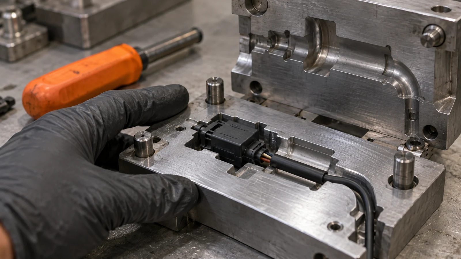
- Locate: mark the defect relative to the gate, vent, parting line, cable exit, and protected component.
- Compare: check multiple samples and determine whether the issue follows a part feature, cavity location, setup, or material lot.
- Verify assembly: confirm the correct revision, component placement, cable routing, cleanliness, and surface condition.
- Inspect the tool: review shutoffs, vents, gates, locating features, and any wear or contamination near the failure.
- Check material and process records: verify grade, handling, startup, settings, and any recent changes against supplier guidance.
- Thay đổi một yếu tố: trial a controlled correction and inspect both the failed area and nearby keep-out features.
For adhesion failures, test the actual substrate combination and surface condition. For a shifted component, focus first on assembly restraint and loading repeatability. For flash at a wire exit, confirm the cable dimensions and location as well as the shutoff design. These targeted checks are more informative than changing several variables at once.
Protect the assembly while correcting the cause
Do not increase molding force or use a more aggressive cleanup method until the component and its interfaces have been assessed. A change can damage electronics, expose conductors, or weaken the seal even if the visible defect improves. Establish criteria for rework, scrap, and revalidation based on the product requirements.
After correction, verify coverage, boundary, component position, adhesion where required, and functional performance. Run any environmental or electrical checks defined for the application before closing the issue. For the process overview, see đúc áp suất thấp để bảo vệ linh kiện điện tử; the defect diagnosis should still be tied to the exact assembly and material.
Câu hỏi thường gặp
Can incomplete coverage be fixed by raising the process setting?
Not without checking flow path, venting, assembly position, material condition, and component limits. A higher setting may create new damage or flash, so use a controlled trial and inspect the complete assembly.
Why does flash appear around a cable exit?
Possible contributors include cable location or size variation, shutoff fit, parting-line condition, and assembly loading. Compare the actual cable and tool condition before selecting a correction.
Does visible encapsulation prove the electronics are protected?
No. Coverage is only one criterion. Adhesion, functional performance, and any required environmental tests must be defined and verified for the application.