
Проектирование гибридных металлопластиковых компонентов требует балансировки соотношений толщины стенок, углов наклона и геометрии удержания металла для предотвращения разрушения соединения. Встраивание металлических шпилек, резьбовых латунных втулок или токопроводящих медных клемм непосредственно в пластиковые бобышки вызывает значительные локальные кольцевые напряжения во время усадки полимера при охлаждении.

Недостаточная толщина стенки бобышки или острые внутренние углы вызывают растрескивание под напряжением вокруг встроенных металлических элементов при механической вибрации дороги или термоциклических испытаниях. Установление стандартизированных правил CAD-проектирования на начальном этапе 3D-моделирования исключает дорогостоящие доработки пресс-форм и обеспечивает высокий выход годных изделий при серийном производстве. Это техническое руководство по DfM анализирует пропорции стенок бобышки относительно вставки, механику накатки и геометрию уплотнения зоны смыкания пресс-формы.
Содержание
Критические параметры CAD: диаметр бобышки, толщина стенки и углы наклона
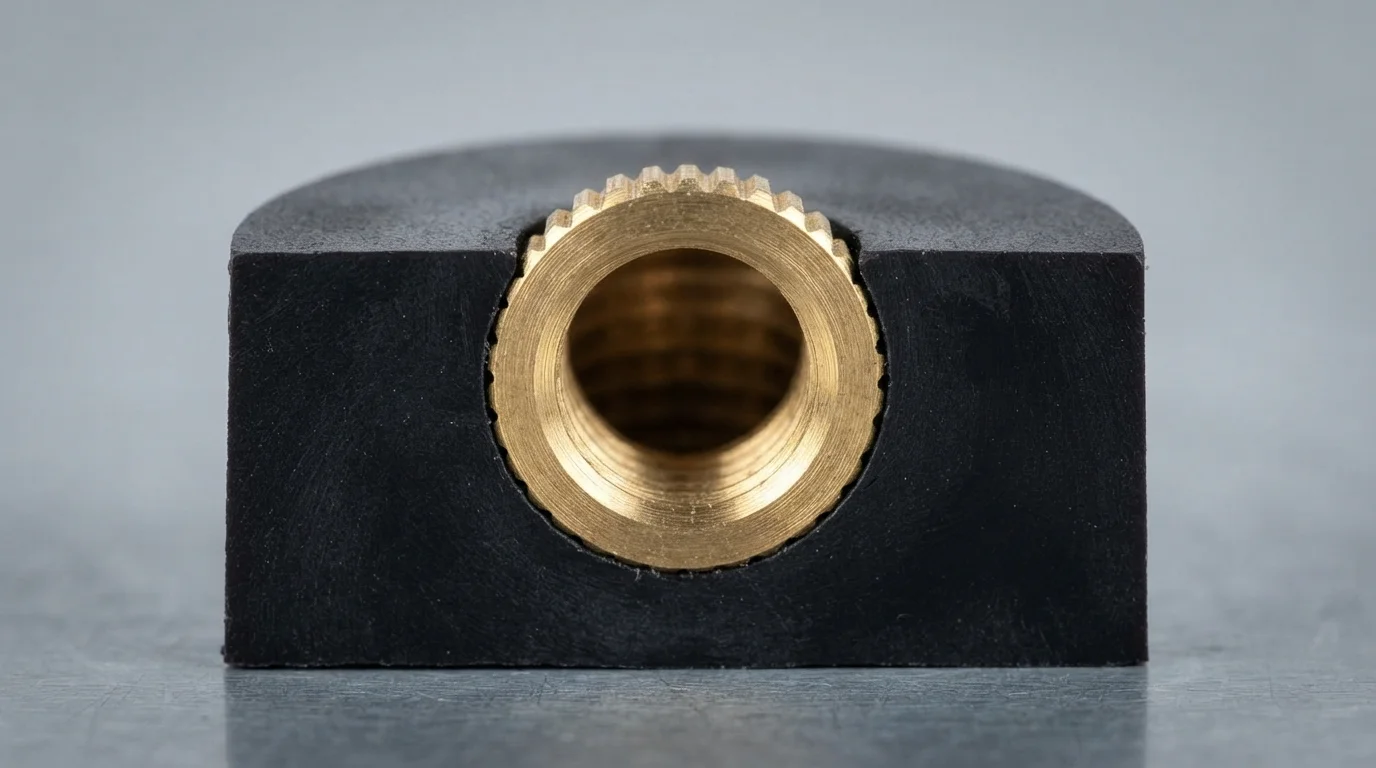
Соблюдение всеобъемлющих рекомендаций по проектированию литья с закладными деталями гарантирует, что стенки пластиковых бобышек выдерживают внутренние кольцевые напряжения, возникающие при охлаждении полимера. Эмпирические правила гласят, что наружный диаметр (НД) пластиковой винтовой бобышки должен составлять от 2,0 до 2,5 наружного диаметра встроенной металлической вставки. Поддержание равномерной толщины стенки вокруг вставки предотвращает локальные перепады охлаждения, вызывающие усадочные раковины или растрескивание под напряжением в высокоэффективных термопластах, таких как PA66, PBT, или PC/ABS.
Выбор угла наклона играет решающую роль в чистом извлечении детали из стальной сердцевины. Вертикальные стенки бобышек и стержни требуют минимального угла наклона от 1,0° до 2,0°, чтобы предотвратить появление царапин и задиров при раскрытии формы. Включение щедрых внутренних радиусов в основании бобышки распределяет механическое напряжение, устраняя острые углы в 90 градусов, которые действуют как концентраторы напряжений.
| Параметр проектирования | Рекомендуемое руководство по САПР | Физический риск нарушения | Основная стратегия оптимизации |
|---|---|---|---|
| Boss Outer Diameter Ratio | 2.0x – 2.5x Insert Outer Diameter | Hoop stress cracking during cooling | Maintain uniform wall mass around insert core |
| Boss Wall Draft Angle | 1.0° – 2.0° Minimum Taper | Core drag marks & part distortion | Add 1° extra draft for textured outer boss surfaces |
| Base Fillet Radius | 25% – 50% of Wall Thickness | Localized notch stress concentration | Smooth internal boss-to-wall corner transitions |
Knurling Mechanics and Interlocking Feature Design
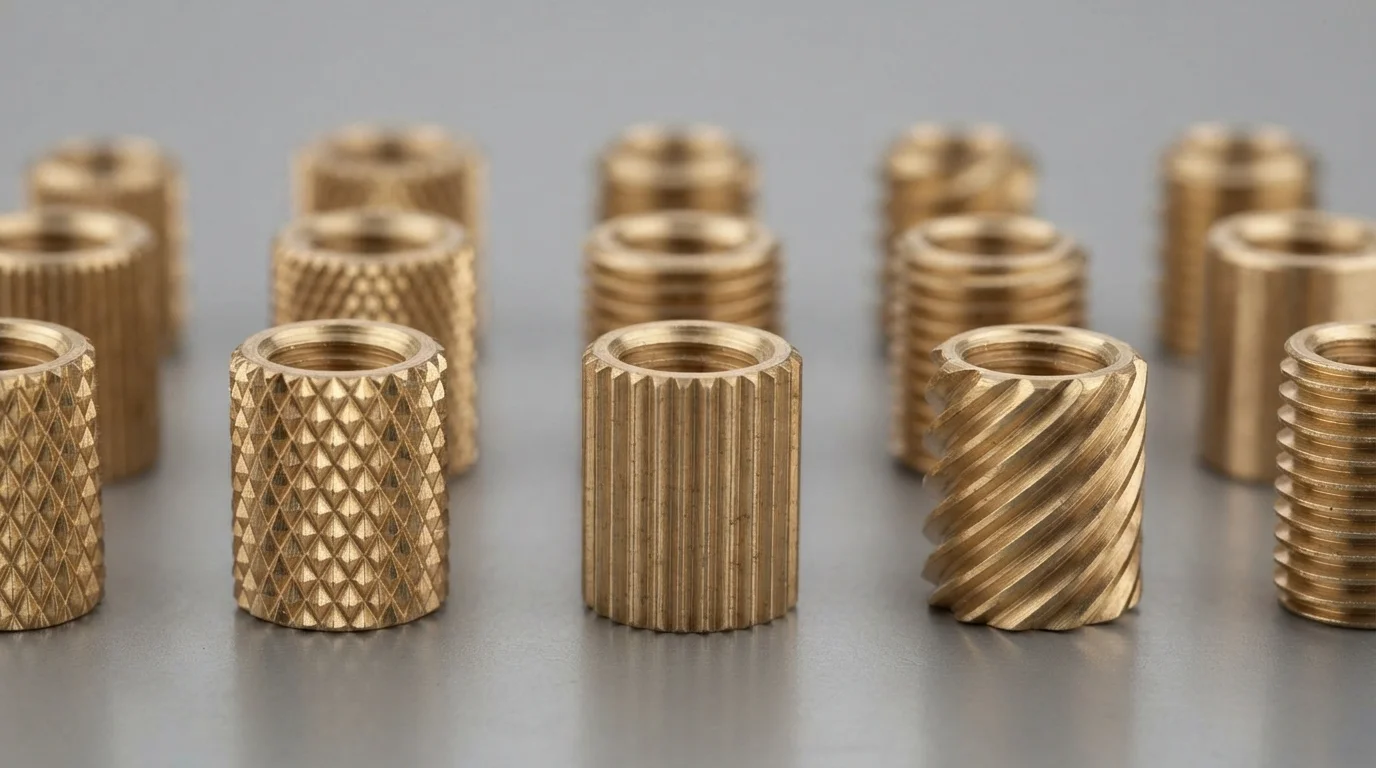
Mechanical interlock design directly governs the rotational torque and axial pull-out resistance of encapsulated fasteners. Pre-molded латунные inserts feature external knurling patterns—such as diamond, straight, or helical knurls—that lock into the cooling polymer. Diamond knurling provides superior bidirectional resistance against combined rotational torque and axial pull-out forces.
Integrating annular grooves or undercut shoulders along the insert length enhances axial retention during heavy mechanical load tests. Molten resin injected under high pressure fills the knurl channels completely, forming a continuous mechanical joint. Executing custom литья с закладными элементами with properly specified knurled fasteners prevents insert spin-out during automated screw assembly.
Key mechanical interlocking design steps include:
- Diamond knurl selection—Specifying cross-hatched knurling maximizes combined torsional and axial holding force.
- Annular groove inclusion—Machining circumferential grooves provides high physical resistance against axial pull-out.
- Knurl depth clearance—Ensuring resin flow fills micro-knurl grooves without air traps maximizes mechanical interlock.
- Insert pilot step—Incorporating a smooth pilot lead-in step simplifies manual or robotic core pin loading.
Designing Mold Shut-Off Lands to Prevent Plastic Flash
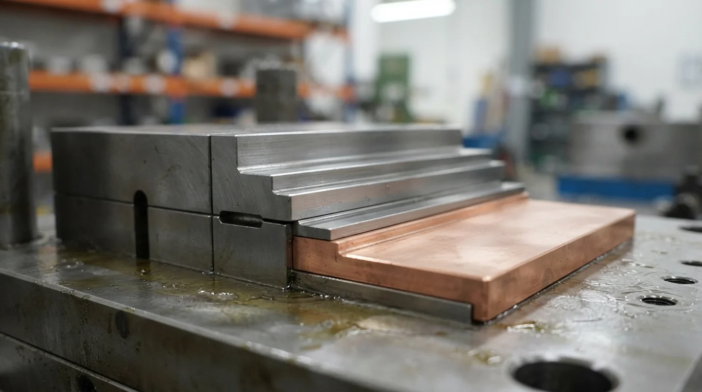
Preventing plastic flash from leaking onto active electrical contacts or threaded bores requires precise tool shut-off land engineering. Shut-off lands represent the mechanical contact faces where hardened mold steel clamps directly against the metallic insert surface.
Designing a flat sealing step measuring at least 0.5 mm wide along the insert shoulder creates a positive physical barrier against high-pressure melt leakage. Incorporating spring-loaded floating core pins compensates for dimensional tolerances in stamped metal inserts, maintaining tight shut-off contact without crushing the metal substrate.
Часто задаваемые вопросы (FAQ)
What is the recommended boss wall thickness ratio for threaded brass inserts?
Recommended boss outer diameter (OD) should equal 2.0 to 2.5 times the outer diameter of the metal insert. Maintaining this ratio provides sufficient plastic wall mass to absorb hoop stresses generated during polymer cooling, preventing localized stress cracking.
Which knurling pattern provides the highest torque-out resistance?
Diamond knurling (cross-hatched) delivers the highest combined resistance against rotational torque and axial pull-out forces. Straight knurls offer high torque-out resistance but require an additional annular groove to prevent axial pull-out.
How do shut-off lands prevent resin from bleeding onto brass threads?
Shut-off lands create a tight mechanical seal between hardened tool steel and the metal insert shoulder. Designing a flat sealing land step measuring 0.5 mm wide prevents molten resin from bleeding past the shoulder into internal blind or through-hole threads.