
La conception de composants hybrides métal-plastique nécessite d'équilibrer les ratios d'épaisseur de paroi, les angles de dépouille et la géométrie de rétention du métal pour éviter toute défaillance physique des joints. L'incorporation de goujons métalliques, de bagues en laiton filetées ou de bornes en cuivre conductrices directement dans les bossages en plastique induit de fortes contraintes circonférentielles localisées lors de la contraction de refroidissement du polymère.

Une épaisseur de paroi de bossage inadéquate ou des angles internes vifs provoquent des fissures de contrainte autour des éléments métalliques encastrés lors des vibrations mécaniques routières ou des tests de choc thermique. L'établissement de règles de conception CAO standardisées lors de la modélisation 3D initiale élimine les modifications d'outillage coûteuses et garantit une fabrication en série à haut rendement. Ce guide technique de conception pour la fabricabilité (DfM) analyse les proportions de paroi entre le bossage et l'insert, les verrouillages par moletage et la géométrie d'étanchéité des plans de joint du moule.
Table des matières
Paramètres CAO critiques : diamètre du bossage, épaisseur de paroi et angles de dépouille
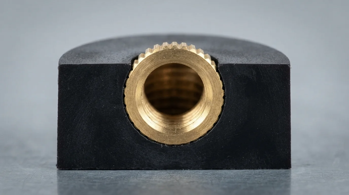
Le respect des directives de conception pour le surmoulage d'inserts garantit que les parois des bossages en plastique résistent aux contraintes circonférentielles internes générées lors du refroidissement du polymère. Les règles empiriques stipulent que le diamètre extérieur (DE) d'un bossage de vis en plastique doit être égal à 2,0 à 2,5 fois le diamètre extérieur de l'insert métallique encastré. Le maintien d'une épaisseur de paroi uniforme autour de l'insert prévient les différences de refroidissement localisées qui provoquent des marques de retrait ou des fissures de contrainte dans les thermoplastiques haute performance comme le PA66, PBT, ou PC/ABS.
Le choix de l'angle de dépouille joue un rôle critique dans l'éjection propre de la pièce hors de l'acier du noyau. Les parois verticales des bossages et les broches de noyau nécessitent un angle de dépouille minimal de 1,0° à 2,0° pour prévenir les marques de traînée et le grippage lors de l'ouverture du moule. L'incorporation de rayons internes généreux à la base du bossage répartit les contraintes mécaniques, éliminant les angles vifs à 90 degrés qui agissent comme des points de concentration de contraintes.
| Paramètre de conception | Directive CAO recommandée | Risque physique en cas de non-respect | Stratégie d'optimisation principale |
|---|---|---|---|
| Boss Outer Diameter Ratio | 2.0x – 2.5x Insert Outer Diameter | Hoop stress cracking during cooling | Maintain uniform wall mass around insert core |
| Boss Wall Draft Angle | 1.0° – 2.0° Minimum Taper | Core drag marks & part distortion | Add 1° extra draft for textured outer boss surfaces |
| Base Fillet Radius | 25% – 50% of Wall Thickness | Localized notch stress concentration | Smooth internal boss-to-wall corner transitions |
Knurling Mechanics and Interlocking Feature Design
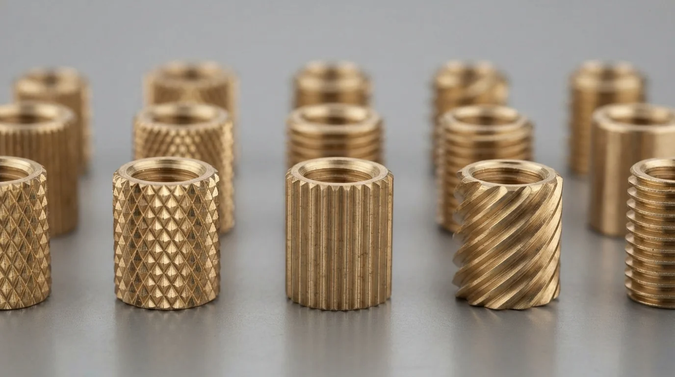
Mechanical interlock design directly governs the rotational torque and axial pull-out resistance of encapsulated fasteners. Pre-molded laiton inserts feature external knurling patterns—such as diamond, straight, or helical knurls—that lock into the cooling polymer. Diamond knurling provides superior bidirectional resistance against combined rotational torque and axial pull-out forces.
L'intégration de gorges annulaires ou d'épaulements en contre-dépouille sur la longueur de l'insert améliore la rétention axiale lors des essais de charge mécanique lourde. La résine fondue injectée sous haute pression remplit complètement les canaux de moletage, formant un joint mécanique continu. Exécuter des moulage par insertion avec des fixations moletées correctement spécifiées empêche la rotation de l'insert lors de l'assemblage automatisé par vis.
Les étapes clés de conception d'un verrouillage mécanique par interpénétration comprennent :
- Sélection du moletage diamant—Spécifier un moletage croisé maximise la force de maintien combinée en torsion et en axial.
- Inclusion de gorges annulaires—L'usinage de gorges circonférentielles offre une résistance physique élevée à l'arrachement axial.
- Dégagement de la profondeur de moletage—Garantir que l'écoulement de résine remplit les micro-gorges de moletage sans piégeage d'air maximise l'interpénétration mécanique.
- Étape pilote de l'insert—L'incorporation d'une étape de guidage pilote lisse simplifie le chargement manuel ou robotisé de la broche de noyau.
Conception de portées d'obturation de moule pour prévenir les bavures de plastique
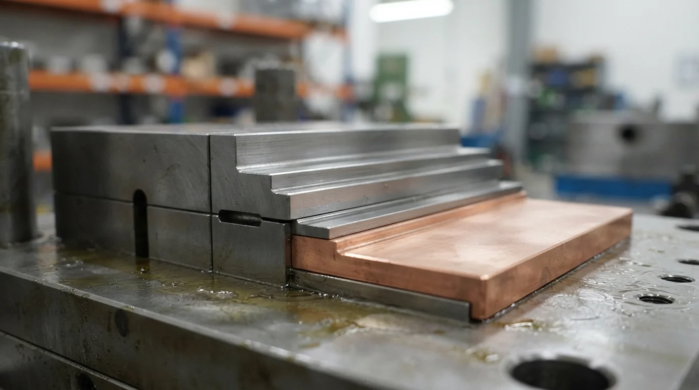
Prévenir les fuites de bavures de plastique sur les contacts électriques actifs ou les alésages filetés nécessite une ingénierie précise des portées d'obturation d'outil. Les portées d'obturation représentent les faces de contact mécanique où l'acier de moule trempé se serre directement contre la surface de l'insert métallique.
La conception d'une étape d'étanchéité plate mesurant au moins 0,5 mm de large le long de l'épaulement de l'insert crée une barrière physique positive contre les fuites de matière fondue sous haute pression. L'incorporation de broches de noyau flottantes à ressort compense les tolérances dimensionnelles des inserts métalliques estampés, maintenant un contact d'obturation étroit sans écraser le substrat métallique.
Questions fréquemment posées (FAQ)
Quel est le rapport d'épaisseur de paroi de bossage recommandé pour les inserts en laiton filetés ?
Le diamètre extérieur (DE) recommandé de la bossage doit être égal à 2,0 à 2,5 fois le diamètre extérieur de l'insert métallique. Le maintien de ce rapport fournit une masse de paroi plastique suffisante pour absorber les contraintes circonférentielles générées lors du refroidissement du polymère, évitant ainsi la fissuration par contrainte localisée.
Quel motif de moletage offre la résistance la plus élevée à l'arrachement en rotation ?
Le moletage diamant (croisé) offre la résistance combinée la plus élevée contre le couple de rotation et les forces d'arrachement axial. Les moletages droits offrent une résistance élevée à l'arrachement en rotation, mais nécessitent une gorge annulaire supplémentaire pour empêcher l'arrachement axial.
Comment les portées d'obturation empêchent-elles la résine de déborder sur les filets en laiton ?
Les portées d'obturation créent un joint mécanique étanche entre l'acier à outils trempé et l'épaulement de l'insert métallique. La conception d'un gradin de portée d'étanchéité plat mesurant 0,5 mm de large empêche la résine fondue de déborder au-delà de l'épaulement dans les filets borgnes ou traversants internes.