
Micro injection molding ejection is not a final mechanical detail; it is the moment when a dimensionally controlled feature becomes an unsupported plastic part. A component can fill correctly and still bend, crack, stick, scatter, or acquire a permanent witness mark during release. For small parts, the ejection concept must continue through collection and packaging.
The best release strategy minimizes force, distributes support, controls where the part remains after opening, and protects the surfaces that govern function. This article follows the part from cavity retention to final collection so the failure point is easier to isolate.
Part journey
Predict Where the Part Will Stay When the Mold Opens
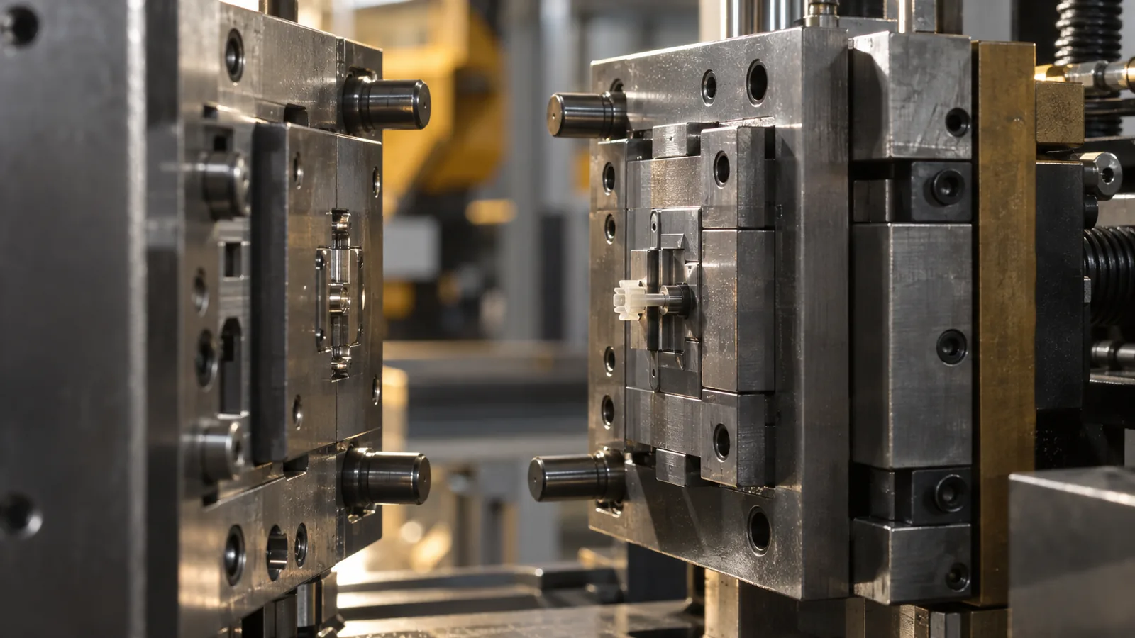
Reliable ejection begins before any pin moves. The tool must control which side retains the part, how strongly it holds, and whether the part remains oriented. Core shrinkage, surface finish, draft, texture, undercuts, gate retention, and cooling balance all influence the result.
A part that alternates between mold halves cannot be collected consistently. It may also collide with the tool or robot because its release position changes from shot to shot. During design review, identify the intended retention surface and compare it with every competing feature that could grip the polymer.
Very small parts introduce another complication: the runner or gate can dominate the release behavior. If the gate breaks unpredictably or the part remains attached to a runner, the collection method must account for separation without damaging the functional feature.
Reduce Release Force Before Adding More Ejectors
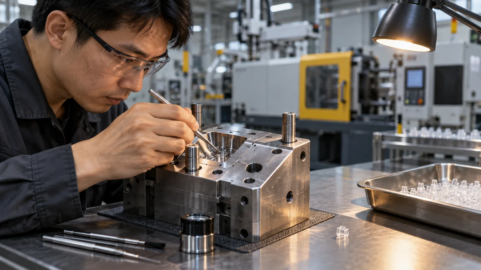
Adding pins can distribute load, but it does not correct every cause of sticking. Excessive retention may come from insufficient draft, roughness in the release direction, deep texture, vacuum formation, core shrinkage, an undercut, high demolding temperature, or distorted geometry.
Review the contact surfaces first. A small improvement in draft or polishing direction may reduce force more effectively than a stronger ejection system. These decisions belong in the услуг по изготовлению пресс-форм на заказ review because draft, polish direction, cooling and ejector access compete for the same tool space. Cooling also matters: a part released too warm may deform under a force that a cooler part could tolerate, while excessive cooling can increase shrinkage around a core.
Decision rule: if ejection force keeps rising during a trial, stop increasing force and determine which surface or pressure condition is retaining the part.
Match the Ejection Method to the Surface That Can Carry Load
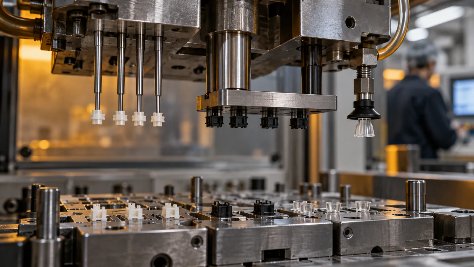
The acceptable contact area—not available mold space—should guide the ejection method. Functional sealing faces, optical surfaces, thin ribs, and miniature gear teeth are poor locations for concentrated force.
| Method | Useful condition | Primary risk |
|---|---|---|
| Small ejector pins | Defined nonfunctional pads with adequate support | Indentation, bending, or pin breakage |
| Sleeve ejection | Round features needing distributed support | Concentricity and witness line |
| Stripper plate | Perimeter or broad-area support | Parting geometry and plate alignment |
| Air assistance | Vacuum release or broad delicate surfaces | Uncontrolled part direction |
| Vacuum or robotic pickup | Controlled transfer into a tray or nest | Pickup consistency and surface contact |
Hybrid strategies are common. Mechanical release may separate the part from the cavity, while vacuum pickup controls orientation immediately afterward. The sequence and timing matter as much as the individual hardware.
Static Electricity Can Turn Release Into a Collection Failure
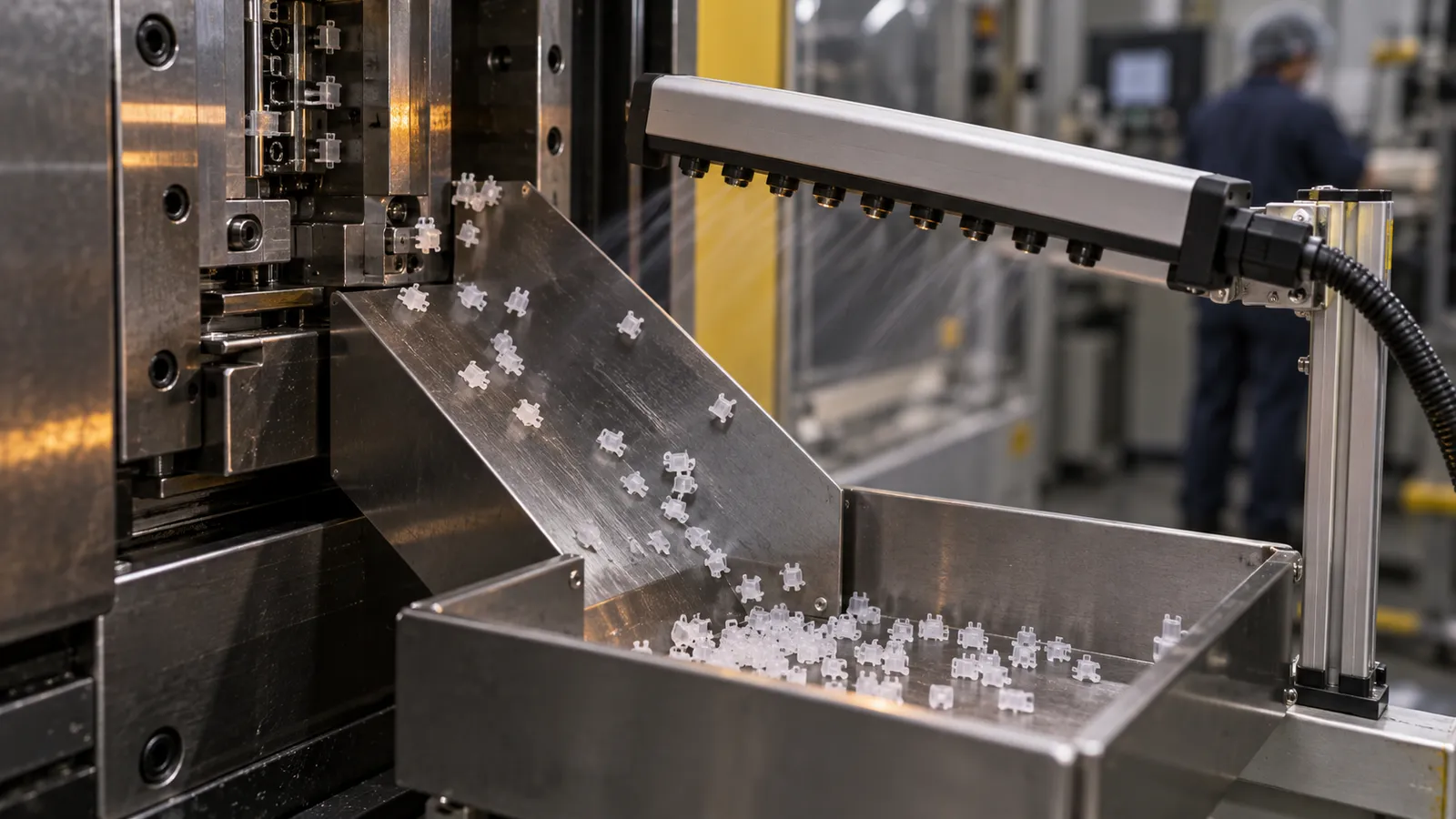
A micro part may leave the cavity and still fail to arrive in the collection tray. Static attraction can hold it on the core, pull it toward a nearby surface, or make multiple parts cling together. Air movement that seems harmless for larger components can scatter light parts.
Collection should be designed as a closed path. The release position, pickup approach, sensor location, transfer speed, tray geometry, grounding, ionization, and packaging material all influence whether every part is accounted for. If the part must maintain orientation for inspection or assembly, random drop collection is rarely sufficient.
For sensitive applications, packaging should also prevent abrasion and particle transfer. A cavity-counted tray or defined nest can support traceability better than a common bin, especially when parts are difficult to separate visually. This is especially relevant when a cleanroom injection molding route is selected to control particulate exposure through collection and packaging.
Use the Damage Pattern to Identify Its Timing
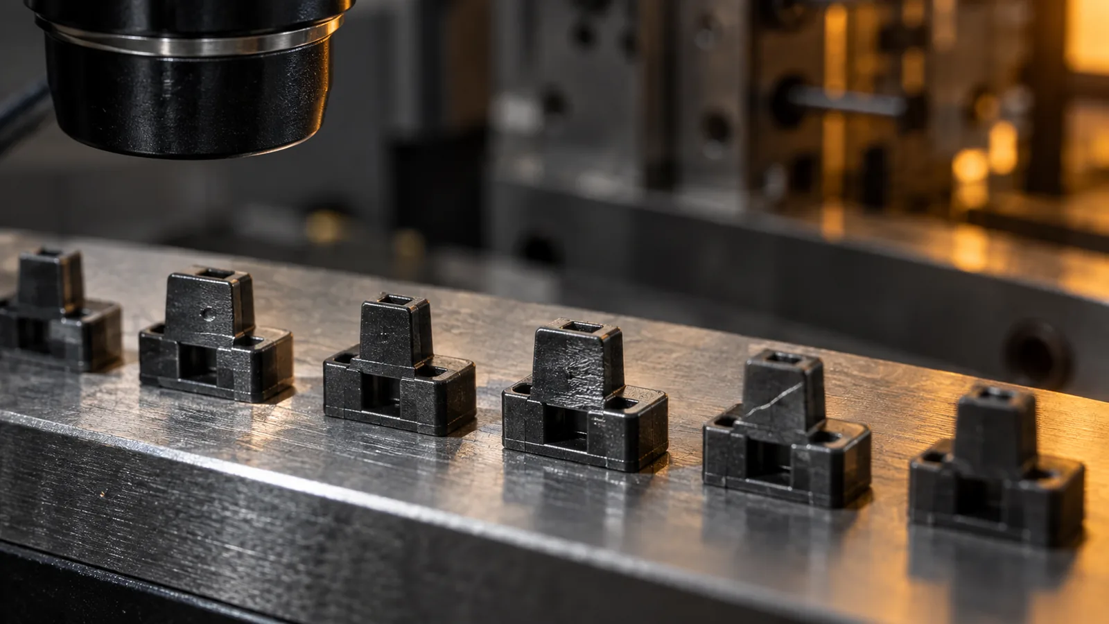
Release damage should be separated from molding distortion. The same bent feature can result from uneven cooling, core retention, ejector force, robot contact, or packaging compression. Evidence from timing helps narrow the cause.
- Damage at one ejector location: inspect contact area, timing, pin alignment, and local temperature.
- Part remains on the core: review draft, finish, shrinkage, venting behind the part, and release temperature.
- Random missing parts: investigate static, air movement, pickup detection, and collection enclosure.
- Scratches after release: compare robot grippers, chutes, trays, and part-to-part contact.
- Shape changes after several minutes: consider residual stress, cooling balance, and unsupported storage.
A high-speed video or staged manual cycle can reveal when the part changes orientation or contacts another surface. Molded dimensions should be checked before and after handling when the damage point is uncertain.
Validate the Complete Release Sequence
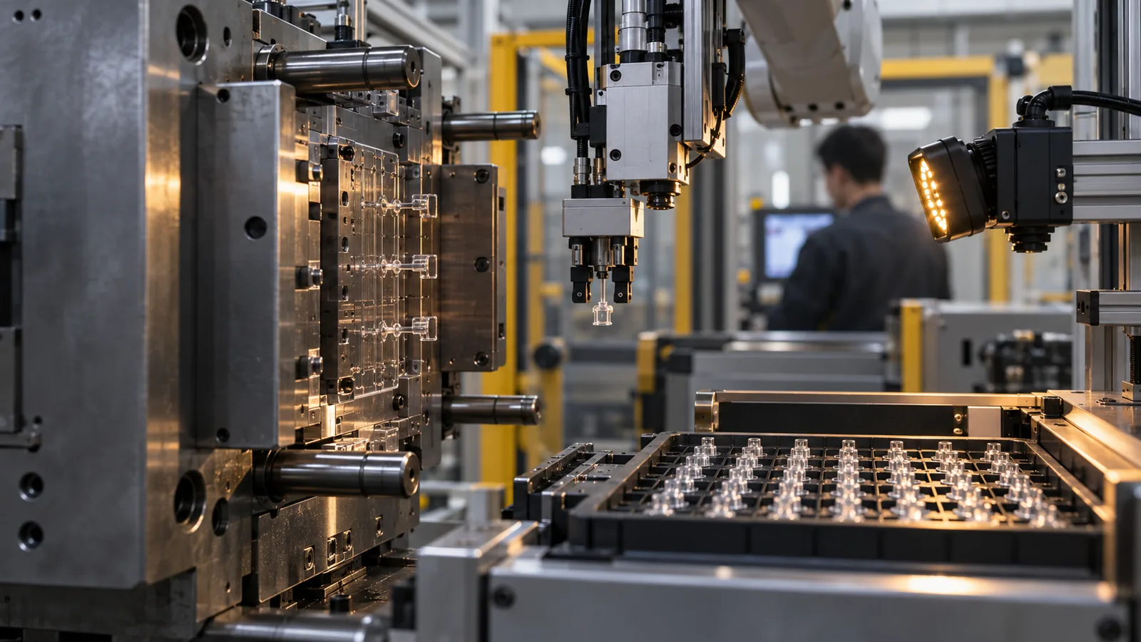
Validation should cover more than a successful mold opening. The goal is repeated release, controlled transfer, accurate counting, and undamaged packaging under normal variation.
- Confirm the intended mold half retains the part every cycle.
- Record release force or a repeatable proxy where practical.
- Inspect ejector marks and functional features under appropriate magnification.
- Challenge normal variation in cooling and mold temperature.
- Verify pickup, presence detection, and rejection logic.
- Run enough cycles to observe static and deposit buildup.
- Measure parts after the actual packaging and conditioning interval.
Процесс Микролитъе под давлением workflow should connect tool release with automated handling and dimensional verification. The site’s контролю качества process can then keep cavity, release damage, measurement, and packaging evidence traceable. Treating ejection as part of that system reduces the risk of approving a cavity that cannot support production.
Часто задаваемые вопросы

Why do micro parts stick even when draft is present?
Draft may be offset by core shrinkage, roughness, texture, vacuum, local undercuts, or a warm release condition. The full contact surface and cooling state should be examined.
Are ejector marks acceptable on micro parts?
Only when their location and depth do not interfere with function, assembly, sealing, appearance, or measurement. The acceptable witness area should be identified on the drawing.
Can compressed air replace ejector pins?
Air can assist release in suitable geometries, but it may not provide enough controlled force or direction by itself. It must also be evaluated for cleanliness and part scattering.
Why should parts be measured after packaging?
Handling and storage can bend delicate features or allow residual stress to relax. Measuring only immediately after molding may miss the condition received by the customer.
What information helps design an ejection system?
Provide functional surfaces, cosmetic limits, allowable witness zones, material, expected temperature, part orientation needs, inspection method, and packaging requirements.