
Designing high-integrity mold structures for metal-plastic hybrid components requires specialized mechanical features that accommodate pre-formed metallic inserts. Metallic fasteners, stamped copper busbars, and electronic pins present physical obstructions inside the mold cavity, demanding precise shut-off lands and robust core retention mechanisms.
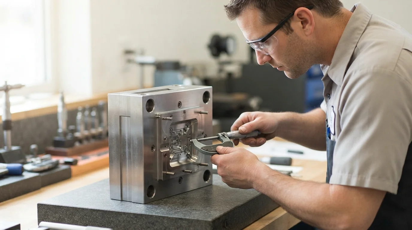
Improper tool steel selection or weak core pin design leads to insert tilt under high injection pressures, resulting in crushed shut-off lands and plastic flash. High-volume automotive and medical encapsulation programs rely on hardened steel cavities, guided ejector plates, and thermal cooling balance to maintain dimensional stability. This technical tooling guide examines core locating mechanisms, cavity steel selection, and SPI Class 101 mold construction standards.
جدول المحتويات
Core Locating Pins, Pneumatic Ejection & Wear-Resistant Shut-Offs
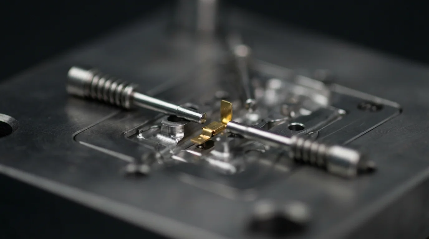
هندسة قوية insert molding tooling depends on integrating mechanical features that anchor metallic inserts securely before mold closure. Precision locating pins fit internal pilot holes or threaded bores tightly, holding 黄铜 أو النحاس inserts true against core steel during high-velocity melt filling. Core magnets or spring-loaded retention pins prevent inserts from dropping during vertical or horizontal mold movement.
Ejection mechanisms must handle encapsulated components gently to prevent bending delicate metal pins or deforming soft plastic walls. Integrating pneumatic ejection sleeves or guided ejector plates applies balanced mechanical lift across the part, preventing terminal pin misalignment during mold opening. Precision shut-off steel lands ground to fitment tolerances under ±0.01 mm block molten resin from bleeding over active electrical contact pads.
Core tooling design principles include:
- Locating pin alignment—Ground pilot pins hold metal fasteners in exact spatial position throughout the clamp-up phase.
- Pneumatic ejector sleeves—Utilizing air-assisted ejection prevents mechanical pin bending on fragile electrical leads.
- Floating shut-off lands—Spring-loaded steel lands absorb metal insert thickness variations without crushing mold steel.
- Guided ejector assembly—Guided ejector plates ensure perfectly parallel movement during part ejection cycles.
25 Five-Axis CNC Machining Centers (±0.01 mm Tooling Tolerance)
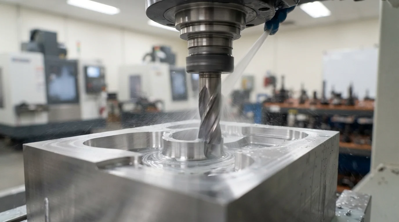
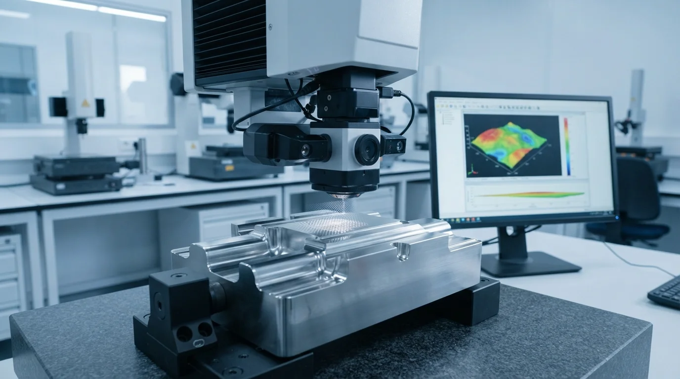
Fabricating intricate core cavities demands high-speed CNC milling and precision EDM electrode cutting. Machining tool steel cores using advanced multi-axis cutters permits deep core pockets, narrow ribs, and 3D parting lines to be cut in a single setup. Eliminating multiple workpiece clampings minimizes cumulative positioning errors, maintaining mold fabrication tolerances of ±0.01 mm.
Selecting premium hardened cavity steels such as الفولاذ المقاوم للصدأ S136 و فولاذ الأدوات H13 provides high-tensile resistance against cavity wear and outgassing. Heat-treating tool steel cores to HRC 48-52 ensures long-term dimensional stability when processing abrasive glass-filled polyamides or flame-retardant thermoplastics.
SPI Class 101 Mold Certification & Maintenance Protocols
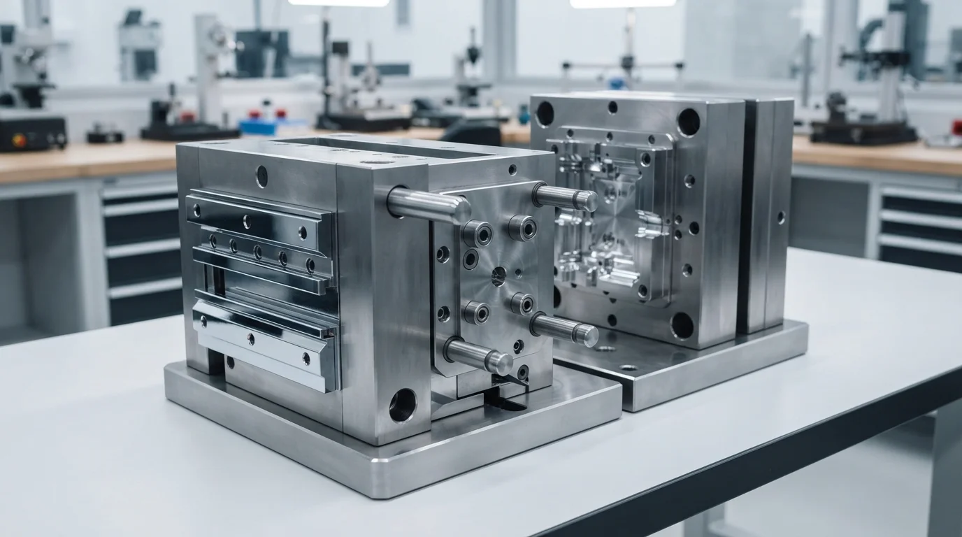
Building SPI Class 101 molds guarantees a production tool lifespan exceeding 1,000,000 molding cycles under continuous series manufacturing. Class 101 tool construction mandates fully hardened stainless or tool steel cores, guided ejector plate assemblies, and wear-resistant slide plates. Precision shut-off steel surfaces are heat-treated to resist abrasive wear, ensuring flash-free encapsulation across long production runs.
يتطلب تنفيذ القولبة الزائدة المخصصة التشكيل بالحقن للإدخالات with certified Class 101 tooling ensures complete part repeatability for high-volume automotive and medical programs. Structured mold maintenance protocols include ultrasonic cavity cleaning, parting line inspection, and core pin wear monitoring at regular production intervals.
| Tooling Specification Metric | SPI Class 101 Production Tool | SPI Class 102 Prototype/Bridge Tool | Primary Tooling Benefit |
|---|---|---|---|
| Cavity Steel Hardness | S136 / H13 Hardened (HRC 48-52) | P20 Pre-Hardened Steel (HRC 28-32) | Resists cavity wear from abrasive glass fibers |
| Ejector System Architecture | Guided Ejector Plates + Pneumatic Pins | Standard Ejector Pins | Prevents core pin binding & terminal pin tilt |
| Guaranteed Shot Lifetime | 1,000,000+ Cycles Guaranteed | 10,000 to 50,000 Cycles | Lowest long-term piece-part tooling amortization |
الأسئلة الشائعة (FAQs)
Why are spring-loaded core shut-offs essential for insert molding tooling?
Spring-loaded core shut-offs compensate for dimensional variations in stamped or turned metal inserts. Metal insert thickness tolerances vary from piece to piece. Floating spring-loaded shut-offs maintain a firm sealing clamp against the metal shoulder without crushing the tool steel or leaving gaps that cause plastic flash.
What is the advantage of S136 stainless steel for insert molding cavities?
S136 is a high-chrome stainless steel offering superior corrosion resistance against acidic gases released by flame-retardant polymers like PEEK, PEI, and PC/ABS. Hardening S136 to HRC 48-52 preserves mirror-polished cavity surfaces and sharp shut-off lands over 1,000,000 molding cycles.
How does guided ejection prevent pin bending during mold opening?
Guided ejection systems utilize hardened guide bushings and pillar posts to keep the ejector plate perfectly parallel to the mold base during movement. Parallel plate movement applies uniform lifting force across all ejector pins, preventing delicate overmolded contact pins from bending or binding during part ejection.