
Micro gear injection molding succeeds when the molded teeth transfer motion quietly and repeatedly—not merely when the cavity appears full. Tooth profile, pitch, runout, bore location, material behavior, and the mating system all contribute to performance. A microscopic visual defect may be harmless, while a small eccentricity can become noise, backlash, wear, or torque variation.
The most useful development sequence starts at the gear pair and works backward to the cavity. That keeps tooling and inspection focused on the features that carry load.
Design premise: a micro gear is a motion component first and a molded shape second.
Contenido
Define the Gear Function Before Tooth Geometry
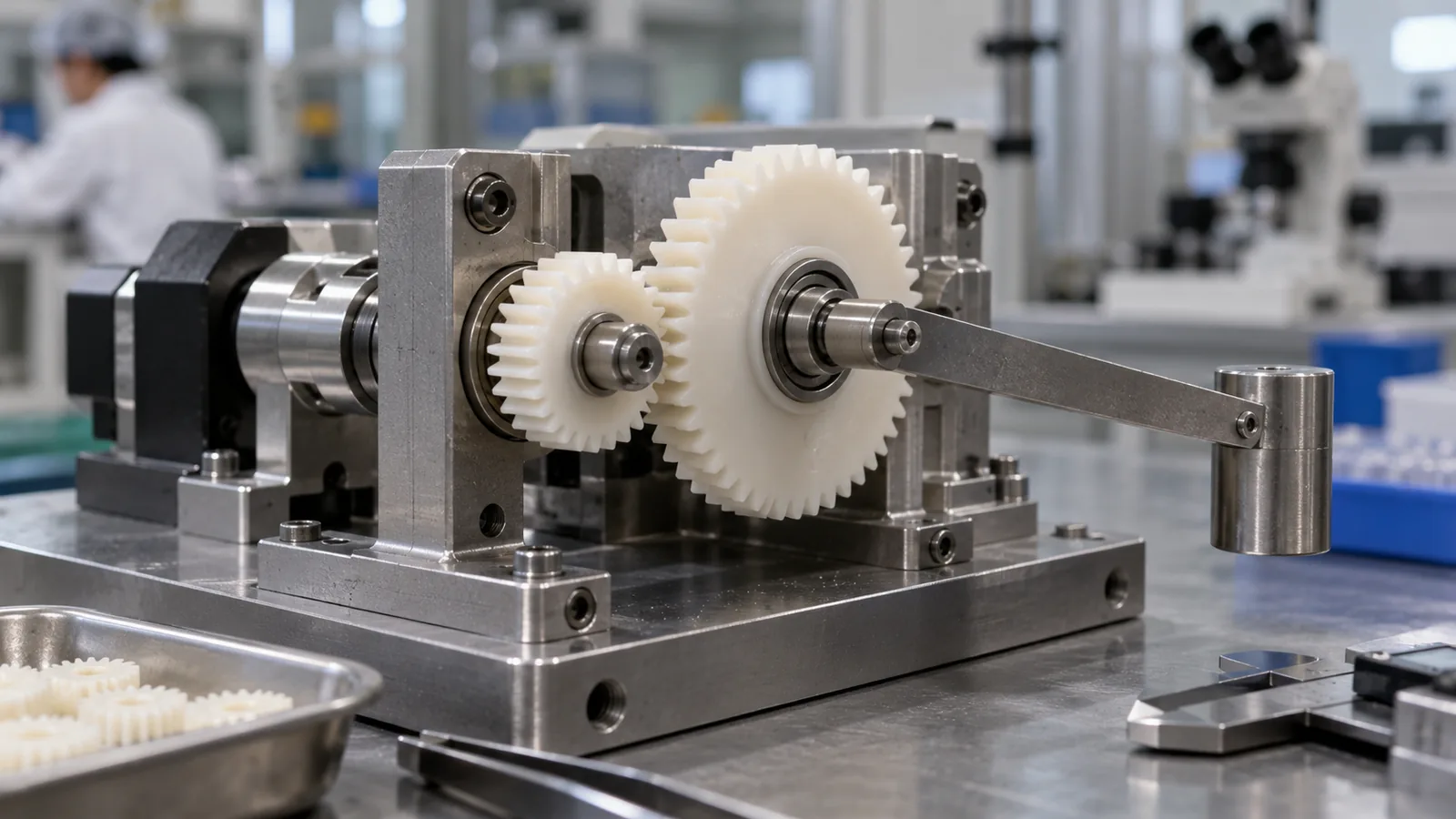
Begin with torque, speed, duty cycle, direction changes, backlash, noise, lubrication, temperature, life, and the material of the mating gear. These conditions determine whether the dominant risk is tooth strength, wear, dimensional drift, creep, or acoustic performance.
Identify the functional datum. If the gear runs on a molded bore, tooth concentricity must be evaluated to that bore. If it is assembled onto a shaft through an insert or press fit, the assembled axis may differ from the cavity axis. A perfect tooth profile measured to the wrong reference does not protect the mechanism.
Document the allowed witness marks and gate-remnant zone. A gate placed on a functional face can disturb seating; one placed near the teeth can introduce local flow or removal risk. The gate decision should be reviewed with assembly and measurement, not selected only for convenient filling.
Why Tooth Filling Changes Across the Gear
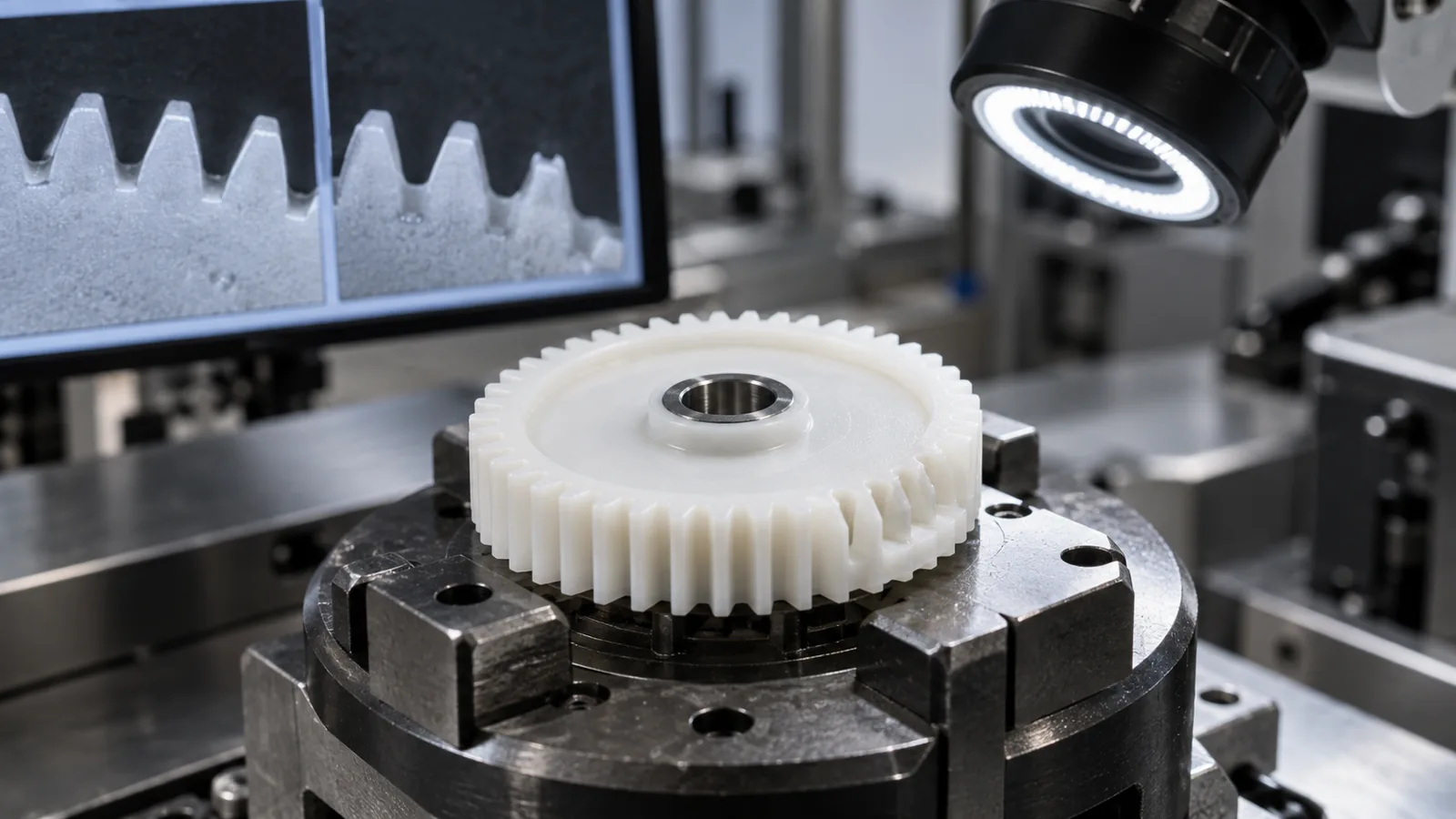
The melt reaching the first teeth may have a different temperature and pressure history from the melt reaching the last. Thin tooth tips freeze quickly, while trapped air at a final-fill tooth can resist complete replication. Weld lines can form where flow splits around a hub and reunites.
Do not judge fill from the gear’s outside silhouette. Inspect tooth thickness, root and tip form, flank continuity, and flash around the circumference. A short-shot study and cavity-pressure evidence can help locate the transition between incomplete replication and an overpacked region.
Gate balance, mold-surface temperature, injection profile, and vent placement should be developed together. Increasing pressure alone may improve one tooth while creating flash elsewhere or shifting bore dimensions.
Choose Materials for Motion, Not Flow Alone
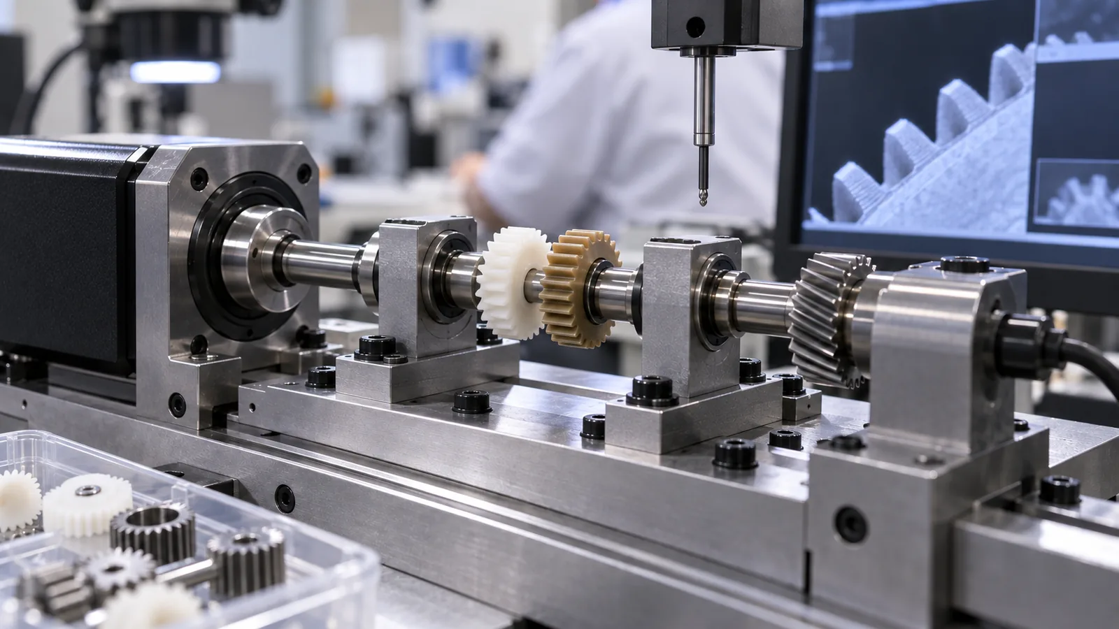
POM (acetal) is often screened for low friction and dimensional behavior, while PA, PBT, LCP, PEEK, and other engineering polymers may be considered for heat, strength, electrical, or environmental needs. The correct grade depends on the system. Moisture conditioning, fiber orientation, lubricant packages, and contact with the mating gear can change wear and noise.
| Design question | Por qué es importante | Evidence to request |
|---|---|---|
| Continuous or intermittent motion? | Changes heat buildup and wear duty | Cycle profile and life test |
| What is the mating material? | Controls friction pair and debris behavior | Paired-material test |
| Is moisture exposure expected? | Can shift dimensions and properties | Conditioned dimensional check |
| Is lubrication permitted? | Changes resin and surface choices | Application-specific wear trial |
Control Concentricity From Cavity to Datum
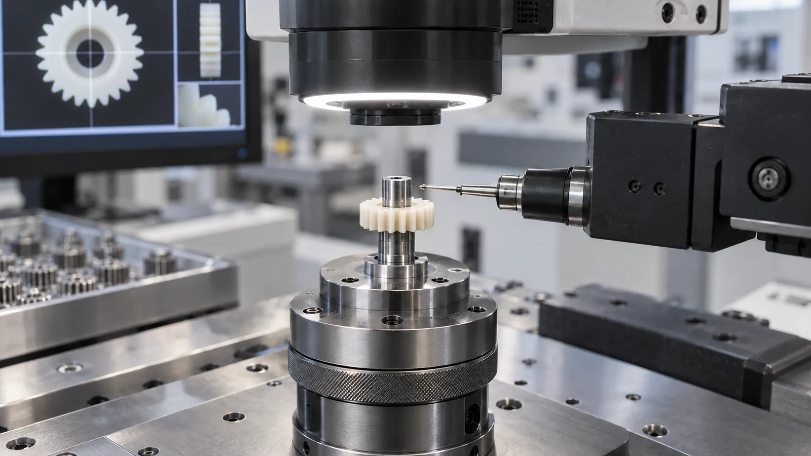
Runout can originate in cavity alignment, core-pin location, insert fit, gate-induced packing, uneven cooling, ejection, or the measurement fixture. The datum chain should therefore be explicit from the mold components to the finished assembly.
A central gate may offer balanced flow but leave a gate feature where the shaft or hub must function. A side gate can free the center while creating directional shrinkage. There is no universally best layout; the choice depends on the tolerance relationship and acceptable secondary work.
Core support and wear deserve attention because a small positional shift represents a large percentage of tooth size. Preventive maintenance should track the tool surfaces that control the bore, tooth cavity, and shutoff rather than relying only on total shot count.
Separate Molding Error From Measurement Error

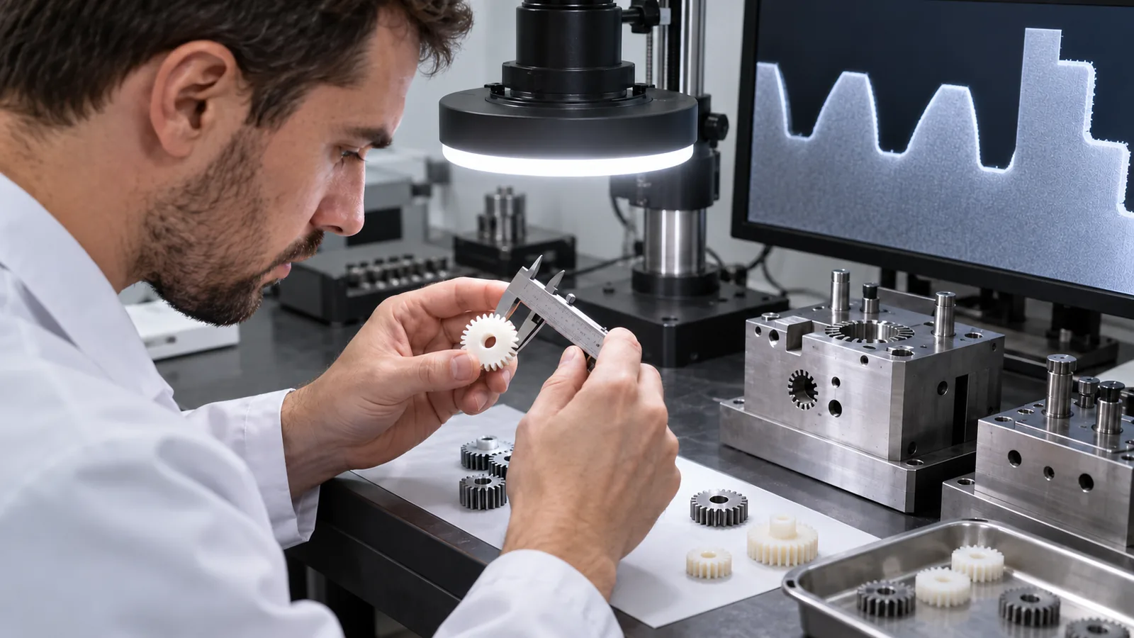
Micro gear measurement can be sensitive to fixturing, focus, edge detection, probe force, and datum construction. Before reacting to a capability result, verify that the method can resolve the tolerance and repeat on the same part.
Profile inspection may use optical or scanning methods, while functional rolling or torque tests can reveal combined effects. These methods answer different questions. A profile map locates geometry error; a functional test shows how the complete gear interacts with its mate.
- Agree on drawing datums and feature definitions.
- Run a measurement-system study with representative parts.
- Compare cavities and molding sequence.
- Correlate geometry with runout, torque, noise, or backlash.
- Measure after the required conditioning period.
Qualify Gears Under Assembly Conditions
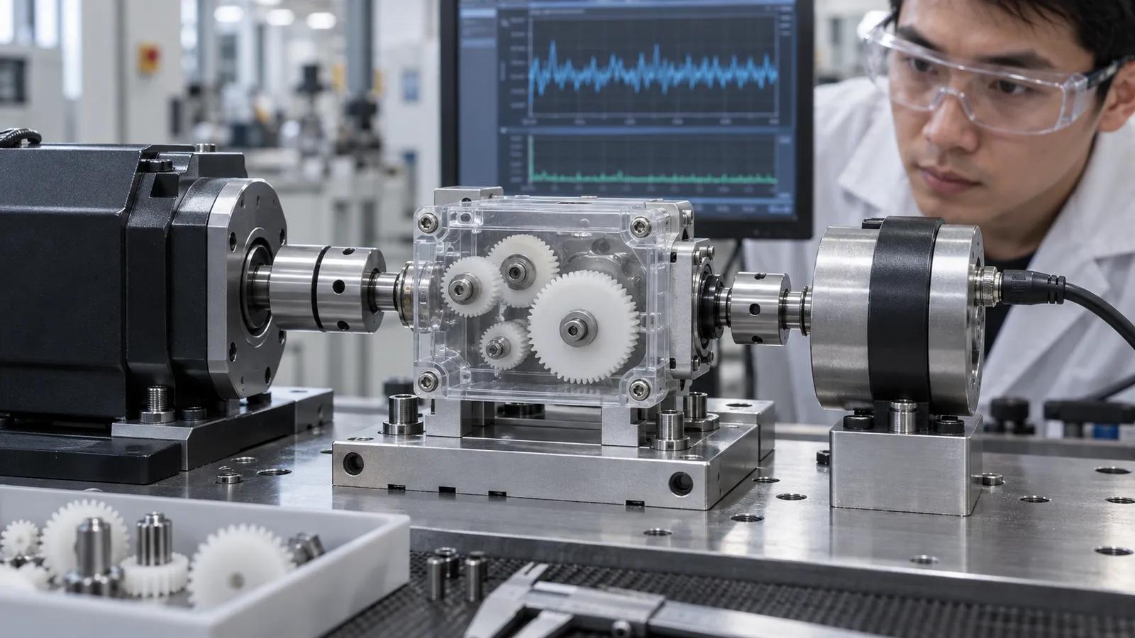
A gear should be tested with the intended shaft, mate, center distance, load, speed, lubrication, and environment. Bench inspection alone cannot reveal every contact pattern or creep effect. If the mechanism is bidirectional, reversal should be included because backlash and tooth contact can change.
During process qualification, monitor feature replication, bore size, runout, part weight, release marks, and cavity-to-cavity differences. Then connect those results to functional testing. For motion systems, a precision robotics gear manufacturing review can also connect the molded gear with shafts, housings, center distance, and duty-cycle evidence. This produces a control plan that protects the mechanism rather than a list of isolated dimensions.
El proceso más amplio Microinyección de plástico process must coordinate tool accuracy, repeatable filling, careful ejection, and suitable metrology. Micro gears make that coordination visible because every error returns once per revolution.
Preguntas frecuentes
What is the most important tolerance on a micro gear?
There is no single answer. Tooth profile, pitch, bore size, runout, and face geometry should be ranked by how the gear mates and carries load.
Can part weight confirm complete teeth?
No. Weight is a useful consistency signal, but local tooth tips can remain incomplete while total weight appears stable.
Why can a dimensionally acceptable gear be noisy?
Noise can come from combined profile error, eccentricity, surface condition, material pair, center distance, housing alignment, or dynamic load.
Should every cavity use the same inspection frequency?
All cavities need traceability, but sampling may be adjusted using validated cavity evidence. A weak cavity should not be hidden inside pooled data.
When is a functional roll test useful?
It is useful when combined tooth and runout effects matter to assembly. It complements rather than replaces feature-level metrology.