
قوالب الحقن الدقيقة لا تقتصر على إعادة إنتاج تجويف صغير فحسب. بل تتحكم في كيفية دخول حجم صغير من البوليمر وتبريده وتحريره وقياسه دون الإضرار بالقطعة. على هذا النطاق، يمكن أن تتداخل بقايا البوابة مع التجميع، وقد يؤدي التهوية الضعيفة إلى حقن ناقص، وقد يتحول خطأ محاذاة بسيط إلى زوائد مرئية.
السؤال التصميمي الحقيقي ليس مجرد ما إذا كان يمكن تشغيل التجويف آلياً. بل ما إذا كان القالب الكامل قادراً على دعم التعبئة والاستقرار الأبعادي والقذف والفحص والإنتاج المتكرر. القالب الذي يبدو دقيقاً في CAD لكن لا يمكن تهويته أو قياسه بشكل موثوق ليس بعد قالباً عملياً للقولبة الدقيقة.
في هذا الدليل:
لماذا يكون القالب أكثر أهمية على النطاق الدقيق
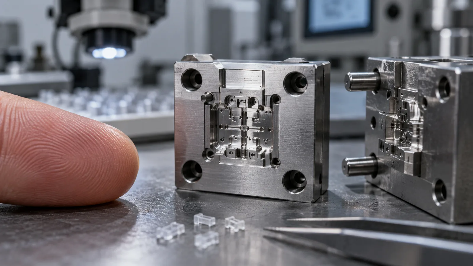
تشمل القولبة الدقيقة حالتين مختلفتين: مكوّن صغير جداً، مثل ترس دقيق أو عنصر موصل، ومكوّن أكبر يحتوي على قنوات أو أضلاع أو نسيج أو تفاصيل بصرية على النطاق الدقيق. قد تبدو هذه الحالات متشابهة في قائمة القدرات، لكنها تفرض متطلبات مختلفة على موقع البوابة والتبريد والتحرير والمناولة والفحص.
تصغير تصميم قالب تقليدي لا يصغّر كل تأثير فيزيائي بالنسبة نفسها. فقد يصبح نظام التغذية كبيراً نسبةً إلى القطعة المقولبة، وتُفقد الحرارة بسرعة عبر مسارات تدفق ضيقة، وقد تمثل بضعة ميكرونات من عدم التطابق جزءاً معنوياً من ميزة وظيفية. لذلك يجب تصميم القالب حول أصغر ميزة حرجة بدلاً من الاعتماد على أبعاد القطعة الإجمالية وحدها.
حكم هندسي: قالب دقيق لا يكون جاهزًا للإنتاج إلا عندما تكون عمليات التعبئة والتحرير والقياس والتجميع قابلة للتكرار كعملية واحدة متصلة.
ما الذي يجب أن يُحدَّد قبل قطع الفولاذ؟

معظم مشكلات الأدوات تصبح مكلفة بعد بدء التشغيل. يجب أن تحدد مراجعة التصميم أولاً الميزات التي تتحكم في الوظيفة، ثم تحدد كيف ستقوم الأداة بتشكيلها وتهويتها وتبريدها وتحريرها والتحقق منها.
- تحديد الأبعاد الوظيفية. فصل متطلبات التجميع والإحكام والتدفق والبصريات والمظهر.
- اختيار منطقة بوابة مقبولة. إبعاد الأثر عن مراجع القياس وحواف الإحكام وأسطح التلامس والأوجه البصرية.
- رسم مناطق التعبئة النهائية. الجيوب العمياء وجبهات التدفق المتقاربة تحتاج إلى مسار مدروس للغاز المحتجز.
- تحديد اتجاه التحرير. زاوية السحب وملمس السطح والقطع السفلية واحتجاز القلب تحدد كيفية خروج القطعة من التجويف.
- إنشاء طريقة الفحص. يجب أن تكون المراجع والوصول للقياس عمليين قبل اعتماد أي تفاوت.
- مراجعة سلوك البوليمر. تؤثر التجفيف والانكماش والتقوية واللزوجة والحساسية لدرجة الحرارة على مفهوم القالب.
يستحق القياس اهتمامًا مبكرًا. لا ينبغي التعامل مع الميزة التي لا يمكن تحديد موقعها بشكل متسق كبُعد رسم عادي. يحتاج نموذج CAD والرسم وتصميم القالب وعملية القولبة وتقرير الفحص إلى مشاركة نفس النظام المرجعي الوظيفي.
بالنسبة للمشاريع التي تتطلب تطويرًا منسقًا للقالب، فإن عملية تصنيع القوالب المخصصة توفر سياقًا مفيدًا لـ DFM والتصنيع الآلي والتجميع والتجربة والتحقق الأبعادي. يجب أن يضيف مراجعة القالب الدقيق بعد ذلك عناصر التحكم الخاصة بالحجم الموصوفة هنا.
كيف تتحكم البوابات والقنوات في التعبئة
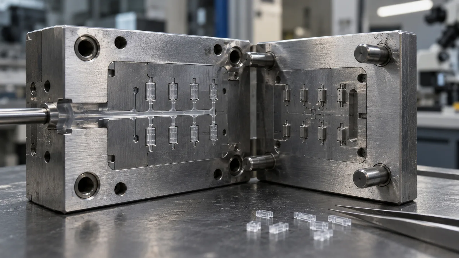
في قطعة تقليدية، قد تكون القناة صغيرة مقارنة بالتجويف. في قطعة دقيقة، يمكن أن يمثل نظام التغذية حصة كبيرة من إجمالي الحقنة. يغيّر هذا كيفية تقييم المهندسين لفقدان الضغط وفقدان الحرارة وزمن المكوث واتساق الحقنة وهدر المواد.
يجب أن يبدأ وضع البوابة بمسار التدفق المطلوب، وليس بأسهل موقع للتصنيع الآلي. يجب أن توفر البوابة وصولًا موثوقًا إلى الميزة الحرجة مع إبقاء الأثر المتبقي بعيدًا عن أسطح التجميع والإحكام والبصريات والقياس.
| قرار التصميم | ما يؤثر فيه | الخطر إذا تم تجاهله |
|---|---|---|
| موقع البوابة | طول التدفق وموضع خط اللحام | تعبئة غير كاملة أو منطقة وظيفية ضعيفة |
| حجم البوابة | القص وفقدان الضغط والأثر المتبقي | إجهاد مفرط أو صعوبة في إزالة بوابة القالب |
| حجم مجرى التغذية | زمن المكوث والتحكم في الحقن | التدهور أو عدم استقرار وزن الجزء |
| توازن التدفق | التناسق بين التجاويف | سلوك تعبئة مختلف بين التجاويف |
| اتجاه البوابة | الاتجاه والانكماش الاتجاهي | الالتواء أو الانحراف الأبعادي |
بالنسبة لأدوات القوالب متعددة التجاويف، يجب تقييم التوازن عبر تخطيط مجرى التغذية والتبريد الكامل. قد يظل التصميم المتماثل هندسياً يمتلئ بشكل غير متساوٍ عندما تختلف ظروف البوابة أو القيود الموضعية أو درجات حرارة التجاويف.
لماذا يُعد التهوية وظيفة تصميمية وليست خطوة تنظيف
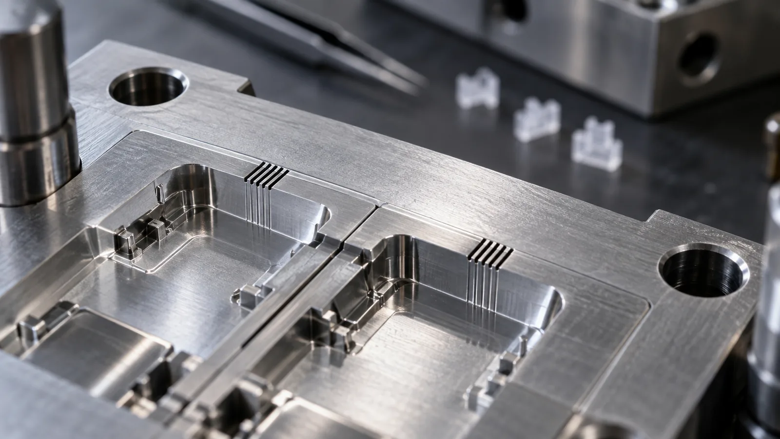
الهواء المحتجز في تجويف دقيق لا يجد مكاناً يذهب إليه ما لم توفر الأداة مسار خروج مُتحكَّم به. قد تؤدي زيادة ضغط الحقن إلى دفع المزيد من البوليمر إلى الأمام، لكنها لا تزيل آلية انضغاط الهواء. قد تكون الأعراض الناتجة حقنة ناقصة أو علامة احتراق أو خط لحام ضعيف أو زوائد أو تكرار غير متسق.
يجب مراجعة التهوية حول مناطق آخر ما يمتلئ، والجيوب المغلقة، والأضلاع الضيقة، والزوايا الحادة، والمواقع التي تلتقي فيها جبهات التدفق. يجب أن يوازن التصميم بين تحرير الغاز والتحكم في الزوائد: ففتحة التهوية المقيِّدة تحبس الهواء، بينما قد يسمح المسار المفتوح بشكل مفرط للبوليمر بالخروج.
A useful diagnosis follows this sequence:
- Locate the defect relative to the expected flow front.
- Check whether it coincides with a last-fill region or trapped pocket.
- Compare vent cleanliness and cavity condition between shots.
- Review fill speed, melt temperature, and mold temperature together.
- Change venting only after the likely mechanism has been confirmed.
حكم هندسي: pressure cannot compensate indefinitely for an air path that was never designed.
Ejection and Handling Need Their Own Plan

A part can fill correctly and still fail while leaving the cavity. Thin walls, tiny cores, deep pockets, and high-friction surfaces can make a conventional ejector layout unsuitable. At this scale, there may be little room for an ejector mark, localized distortion, or uncontrolled release force.
The release plan should answer three separate questions:
- How will the molded part separate from the cavity?
- How will it be supported while leaving the tool?
- How will it be collected without mixing, scratching, or losing parts?
Possible measures include balanced ejector placement, stripper action, controlled draft, surface treatment, vacuum retrieval, and robotic collection. The right choice depends on geometry and material; no single ejection method is universally superior.
Static charge can make very small plastic components cling to the mold, ejectors, or packaging surface. In that situation, the apparent molding problem may actually be a handling problem. Collection trays, grounding, air movement, and packaging orientation should be reviewed before production begins.
Material Behavior Changes the Tooling Strategy
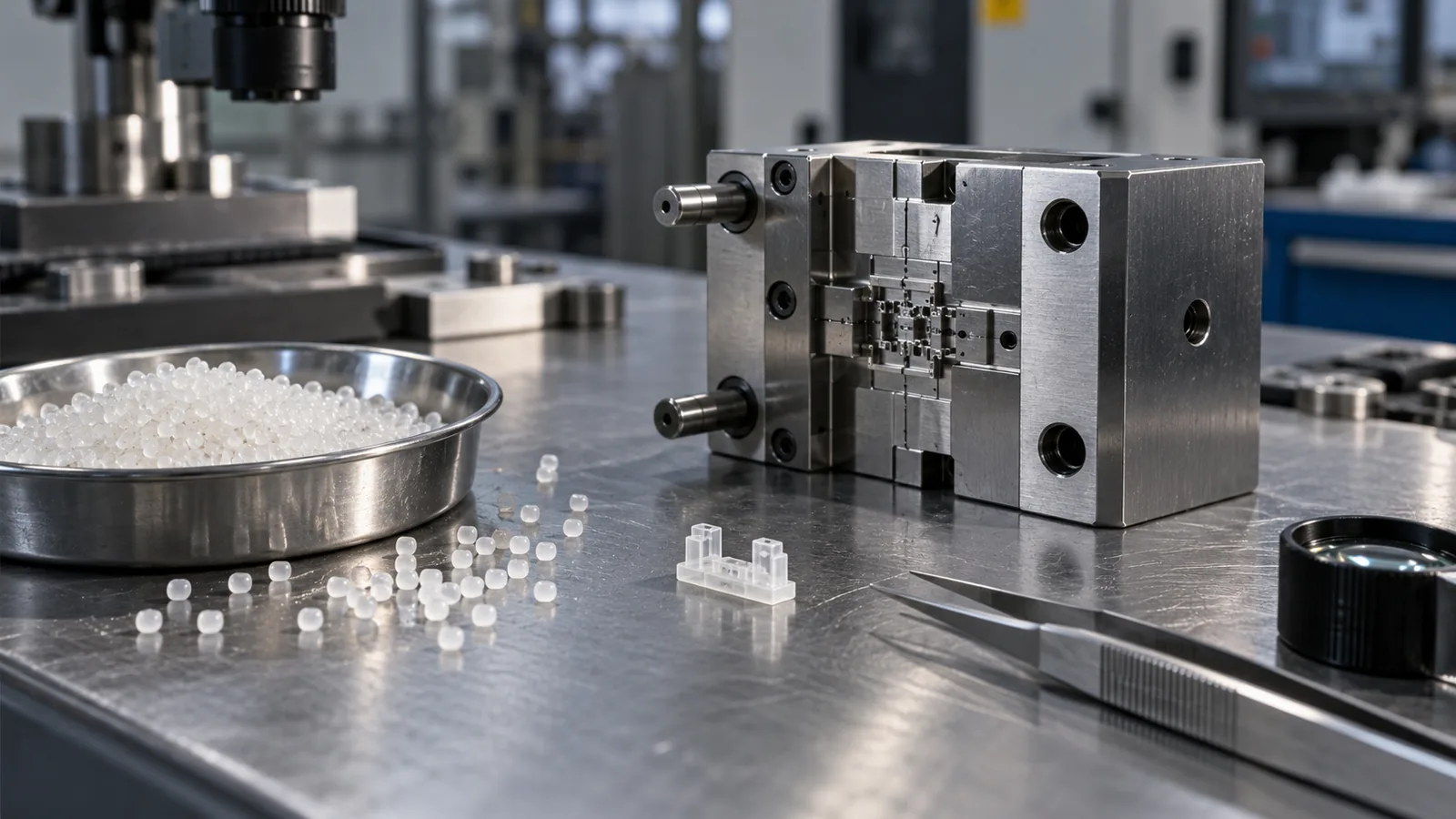
Material selection affects more than final part properties. It changes how the tool must manage flow, heat, shrinkage, wear, release, and dimensional verification.
High-flow polymers may help fill narrow paths, but they can make flash, gate vestiges, and molecular orientation more important. Reinforced grades can improve stiffness while increasing tool wear and making directional shrinkage more visible. Hygroscopic polymers require controlled drying because moisture can alter appearance, strength, and process stability.
A material decision should be checked against the complete requirement set:
- Functional dimensions and assembly fit
- Temperature and chemical exposure
- Wear, friction, or fatigue requirements
- Shrinkage and orientation behavior
- Appearance or optical performance
- Drying and handling sensitivity
- Inspection and documentation needs
For sensitive engineering polymers, the process should avoid unnecessary residence time and dead zones in the feed system. Transparent components add another layer: cavity finish, contamination control, weld-line location, and inspection conditions can matter as much as nominal filling pressure.
A Practical Design Review Sequence

1. Separate Part Size From Feature Size
Record whether the challenge is overall mass, a thin wall, a micro hole, a fine texture, or a tolerance-sensitive interface. A larger part with micro features may need a different tool architecture from a truly miniature component.
2. Establish the Measurement Strategy
Define datums, critical dimensions, sampling points, and the measurement method. Measurement uncertainty should be considered before releasing a tight tolerance, not after the first trial produces conflicting reports.
3. Build the Flow and Venting Concept
Choose a gate location, identify likely last-fill zones, and decide how gas can escape. When flow behavior remains uncertain, simulation or a staged trial is more useful than premature steel adjustment.
4. Design for Release and Collection
Review draft, core retention, ejector access, surface finish, static behavior, and packaging orientation as one handling chain. A successful shot is not useful if the component is damaged or lost immediately afterward.
5. Make the First Trial Answer the Hard Questions
The initial trial should test the assumptions carrying the most risk: filling of the critical feature, flash control, part release, cavity balance, and measurement repeatability. Confirming only that polymer enters the cavity does not prove the tool is ready for stable production.
يجب أن تنسق القولبة بالحقن الدقيق page explains how tooling, molding, handling, and metrology fit together. This article focuses specifically on the mold decisions that determine whether those capabilities can be applied consistently.
الأسئلة الشائعة

Are Micro Injection Molds Only Used for Very Small Parts?
No. They can also form micro-scale channels, ribs, optical textures, holes, or other precision features on larger components. The tooling strategy depends on the smallest functional feature and its required repeatability, not only on total part weight.
What Is Usually the First Tooling Risk to Review?
Filling and air evacuation are early priorities because narrow flow paths can freeze quickly and trapped gas can prevent complete replication. Gate position and venting should be understood before cosmetic details are finalized.
Can a Standard Mold Design Simply Be Scaled Down?
Not reliably. Scaling changes the relationship between runner volume, cavity volume, heat transfer, vent dimensions, ejection force, and measurement resolution. Familiar design principles still apply, but their acceptable limits must be reassessed.
Should Material Selection Happen Before Mold Design?
The two decisions should develop together. Polymer behavior affects flow, shrinkage, wear, drying, and release, while mold geometry determines how those behaviors appear in the finished component.
What Should a Buyer Provide for an Initial Review?
Provide the 3D model, 2D drawing, material or material family, expected volume, critical dimensions, operating environment, appearance requirements, and known assembly or inspection constraints. These details help separate tooling risks from material, process, and measurement risks.