
Viscosity in a thin cavity is not a fixed material number. As the melt moves faster through a narrow section, shear rate changes the apparent viscosity, heat generation, pressure demand, and molecular orientation. That is why a process that fills slowly in a test piece may behave differently in a long thin part. Understanding the relationship helps engineers choose a gate, resin, and injection profile without treating speed as a universal cure.
What Shear Rate Means in the Cavity
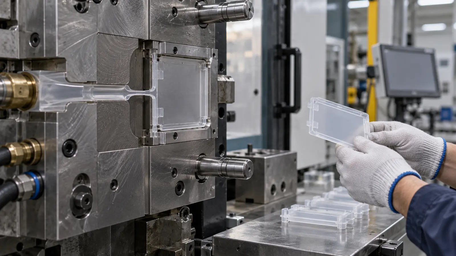
Shear rate describes how quickly adjacent layers of melt move relative to one another. Near the mold wall, the material slows as it cools. In the center of the flow channel, it moves faster. A narrow wall and a high flow rate can therefore create a strong velocity gradient and a different apparent viscosity from the value suggested by a simple material comparison.
The result depends on polymer chemistry, temperature, wall thickness, flow rate, gate dimensions, and the distance the melt must travel. The same grade can show different pressure and surface behavior when the geometry changes.
Why Thin Walls Amplify the Effect
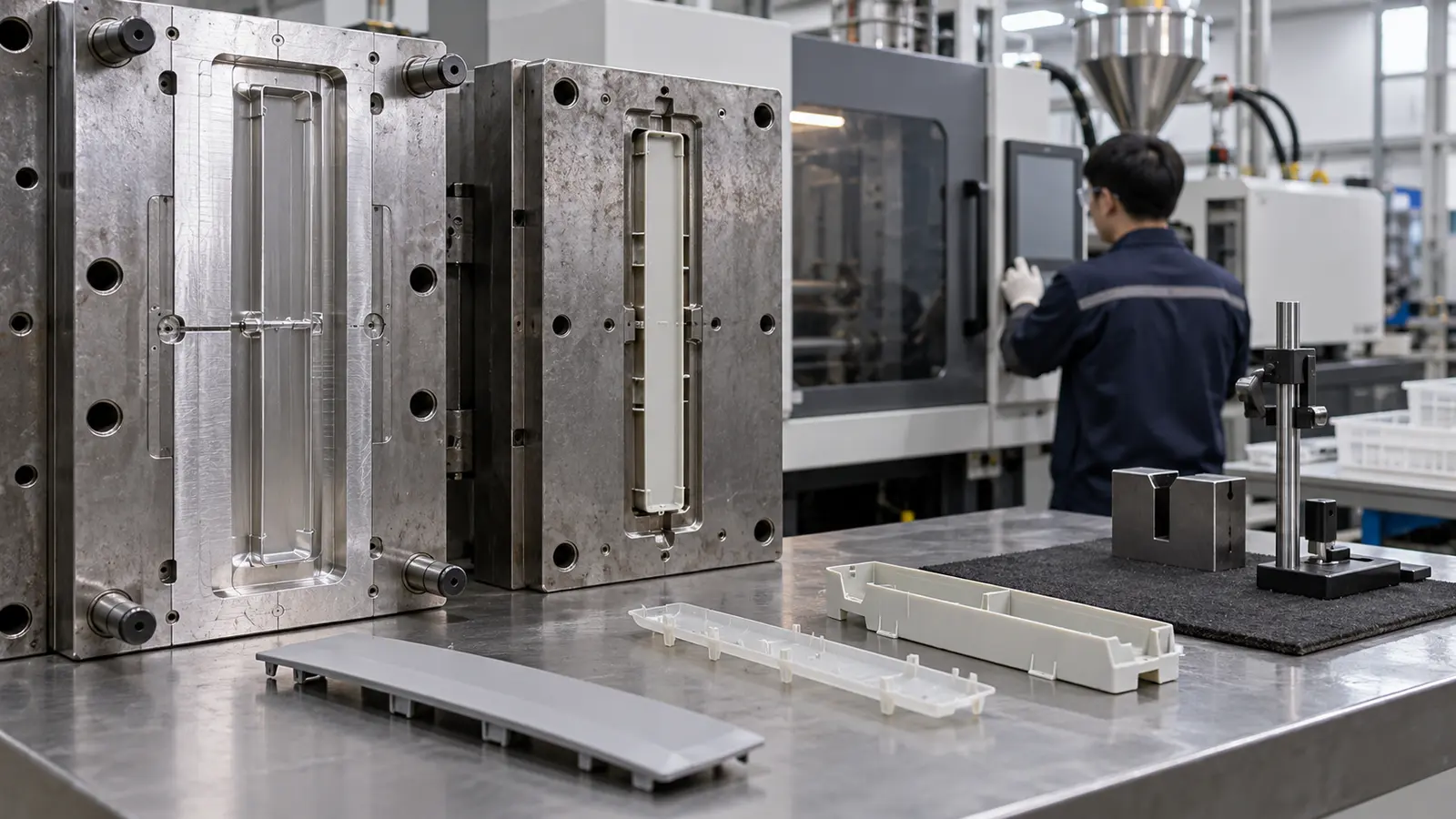
Thin sections lose heat quickly and leave less room for the melt to flow around a growing frozen layer. Increasing injection speed may help the flow front reach the end before freeze-off, but it also changes shear heating and orientation. A narrow process window can appear when the cavity is long, the gate is small, or venting is weak.
| Observed change | Possible mechanism | Review direction |
|---|---|---|
| Pressure rises sharply near end-of-fill | Freeze-off or excessive flow resistance | Gate, mold temperature, flow length, and material window |
| Gloss changes along the wall | Different cooling or shear history | Surface temperature, speed profile, and venting |
| Flatness changes after ejection | Orientation or uneven shrinkage | Cooling balance and flow direction |
Which Molding Signals Matter
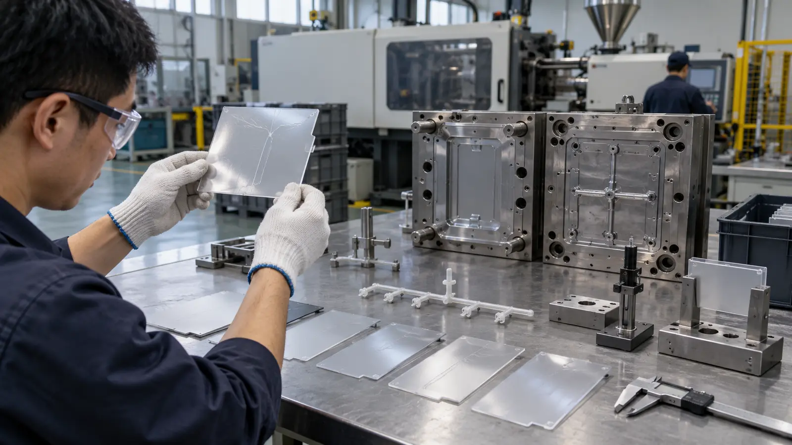
Do not diagnose a shear-related issue from one defect alone. Compare machine pressure, fill pattern, gate condition, surface appearance, weld lines, flash, and dimensional results. A short shot may come from freeze-off or trapped air. A glossy streak may come from local shear and temperature, but it may also point to contamination or an unstable surface condition.
- Track pressure and fill-time changes across repeated shots.
- Inspect the end-of-fill area and the region near the gate.
- Compare flatness and critical dimensions after a consistent cooling period.
- Separate cavity imbalance from a material-wide process response.
How to Control the Process
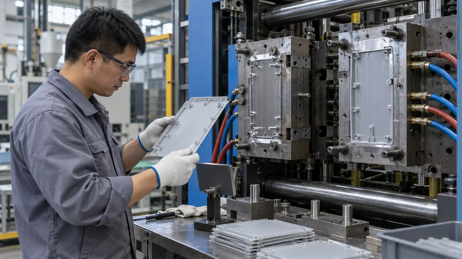
Process control begins with a sound tool and material setup. Gate design, venting, mold temperature, drying where applicable, and a stable injection profile work together. Changing injection speed alone can hide a weak design for one condition and expose it again when the resin lot or ambient temperature changes.
- Use the material supplier’s processing range as a boundary, not a guarantee.
- Set the fill profile to avoid premature freeze-off while monitoring pressure and surface response.
- Confirm that vents can evacuate air at the actual last-fill locations.
- Use cooling and ejection settings that protect flatness and critical mating features.
- Record the relationship between speed, pressure, temperature, and part quality.
A moldability review for القولبة بالحقن للجدران الرقيقة should include these interactions. The objective is a repeatable process window, not a single successful shot at an aggressive setting.
How to Review a Stable Window
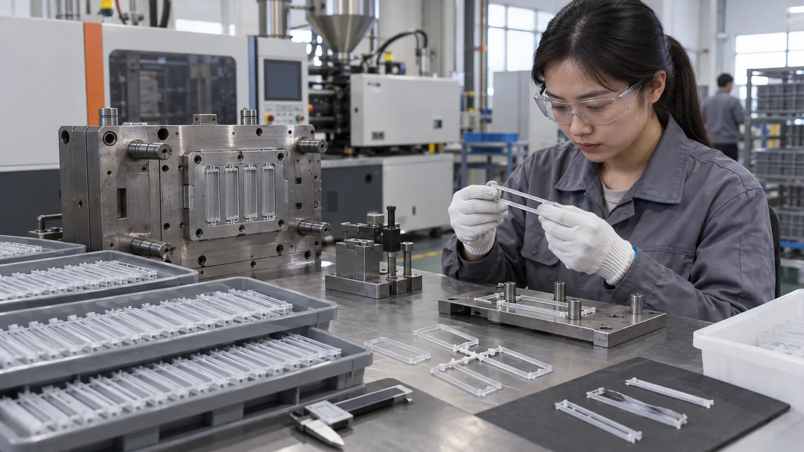
A stable window is demonstrated when reasonable changes in normal inputs do not push the part immediately into short shot, flash, severe gloss variation, or unacceptable warpage. Review the window across repeated cycles and, when appropriate, across cavities and material lots.
Use the result to decide whether the next improvement belongs in the tool, the material selection, or the process sheet. If the window is too narrow, geometry or gate changes may provide more durable improvement than adding more pressure.
Use the Defect Pattern Before Changing the Speed
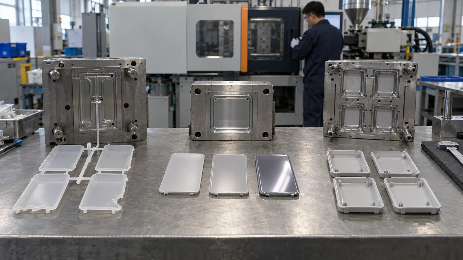
Shear-related defects should be diagnosed from their pattern. A defect that follows the flow direction suggests a different review from a defect that appears only at the end of fill, near a weld line, or in one cavity. Machine pressure and injection speed are evidence, not the diagnosis.
| Pattern | First review | Do not assume |
|---|---|---|
| Only last-fill region fails | Venting, freeze-off, and flow length | That the whole resin is unsuitable |
| Gloss changes along flow | Surface temperature and speed profile | That more pressure will improve it |
| One cavity differs | Balance, vent condition, and local cooling | That the machine is unstable everywhere |
A structured تحليل DFM لقولبة الحقن helps separate a geometry problem from a process problem. Once the part is stable, the لضبط الجودة should define the inspection points that prove the improvement remains repeatable.
FAQ: Shear Rate in Thin-Wall Molding
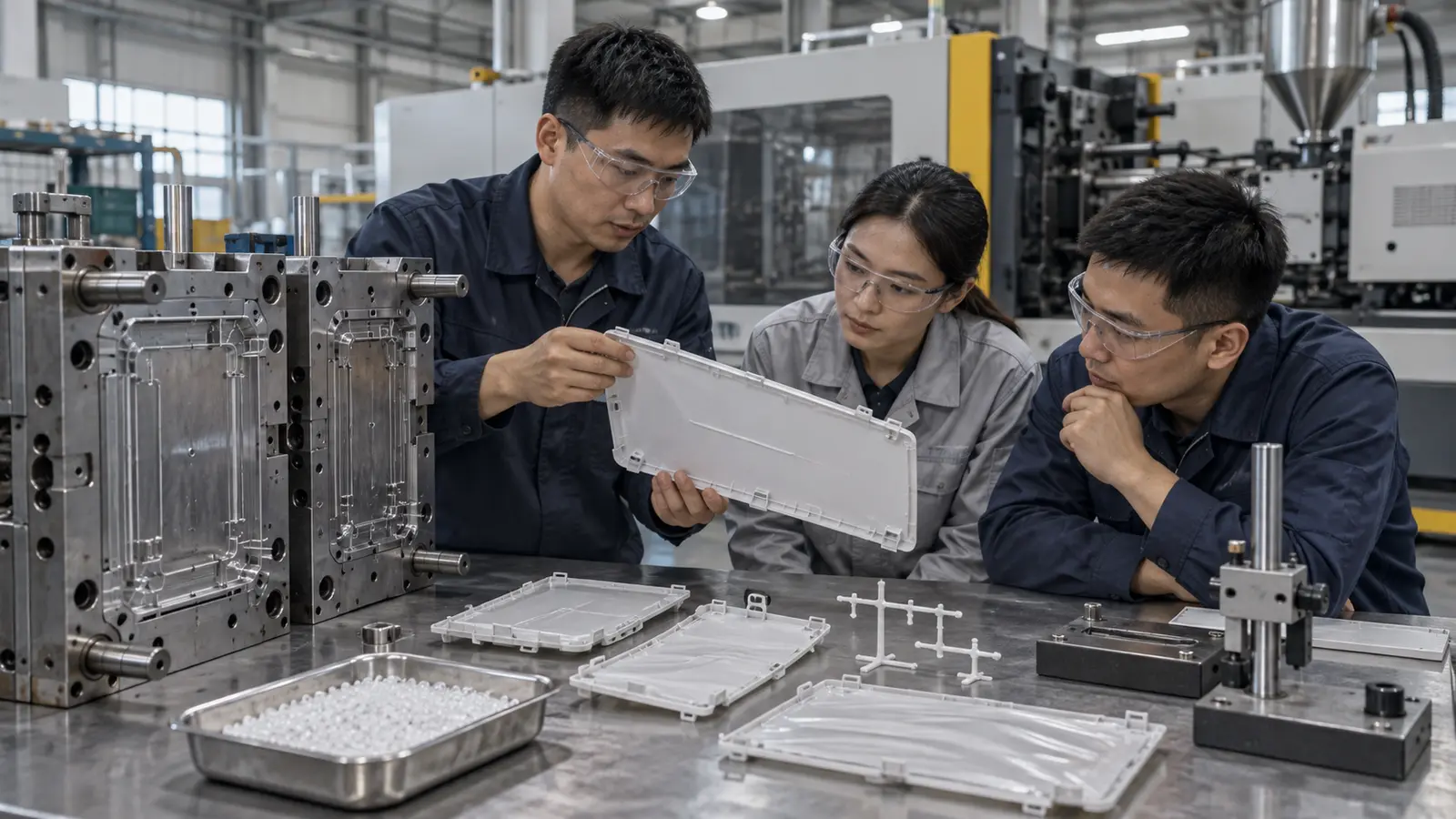
Does faster injection always reduce viscosity?
Many polymers show shear-thinning behavior, but the practical result still depends on temperature, geometry, pressure loss, and the material’s rheology. Faster filling can also increase heating, orientation, and defect risk.
Can a machine pressure increase solve the problem?
It may delay a short shot, but it does not remove a bad gate, trapped air, uneven cooling, or an unsuitable material choice. The root cause should be identified before pressure is increased.
Why inspect parts after cooling?
Orientation, shrinkage, and thermal gradients can continue to affect flatness and fit after ejection. A consistent inspection condition makes comparisons more meaningful.