
Microfluidic channel injection molding should be judged by how the finished device moves fluid, not by whether the cavity produces a clear plastic outline. Channel depth, width, corner shape, roughness, roof flatness, particle condition, and bonding deformation can all change hydraulic resistance or disturb flow. A correctly molded half can still become a poor device after sealing.
The practical development target is a repeatable channel profile through molding, demolding, bonding, and functional testing. The following review keeps those stages connected.
Device pathway
Channel Replication Must Be Judged as a Profile

A channel described only by nominal width and depth is incomplete. Sidewall angle, bottom radius, edge roll-off, local sink, surface texture, and roof distortion can alter flow or bonding. Measure the cross-section at defined locations rather than accepting one attractive microscope image.
Replication may vary along the channel. A feature near the gate can receive a different thermal and pressure history from one near the final-fill region. Intersections, turns, reservoirs, and transitions can also trap gas or cool differently. The inspection plan should sample the locations most likely to affect fluid resistance and mixing.
Functional tolerances should reflect the device. If flow resistance is the output, a permitted width change may depend on the accompanying depth change. Independent plus/minus limits can allow a channel combination that does not meet the hydraulic requirement.
Gate Distance Changes What the Channel Receives
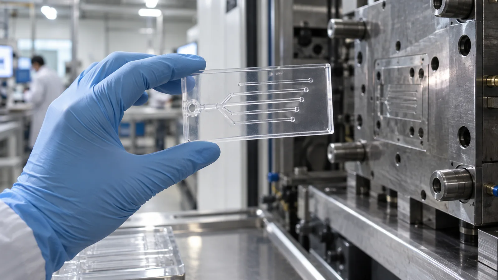
As polymer travels from the gate, it loses heat and pressure while its flow orientation evolves. Fine channels far from the gate may replicate less completely, especially when a thin base wall feeds them. Moving the gate can improve one region while introducing a gate vestige, weld line, or stress near another.
A useful trial compares feature profiles by distance and orientation from the gate. Short-shot samples reveal the fill sequence; cavity-pressure data can show when the feature region is reached; optical or profile measurements confirm what was replicated. These pieces of evidence should agree before the process is widened.
Do not use overall part weight as a channel measurement. A plaque can reach a stable weight while local channel edges remain incomplete.
Material Choice Includes Optics and Bonding

COC, COP, PC, PMMA, and other polymers may enter a microfluidic shortlist depending on optical needs, chemical contact, temperature, sterilization, cost, and bonding route. The COC TOPAS 5013 material page is one useful grade reference, but the best choice remains application-specific. Transparency alone does not prove low autofluorescence, chemical resistance, or compatibility with a surface treatment.
| Device need | Material question | Qualification evidence |
|---|---|---|
| Optical detection | Transmission, haze, fluorescence, stress | Test at the operating wavelength after bonding |
| Chemical contact | Swelling, cracking, extraction, absorption | Exposure using the real fluid and time |
| Thermal or solvent bonding | Softening and channel collapse | Sectioned sealed-device profile |
| Sterilization | Color, brittleness, dimensions, surface chemistry | Post-cycle functional validation |
Demolding Can Change a Correctly Filled Channel
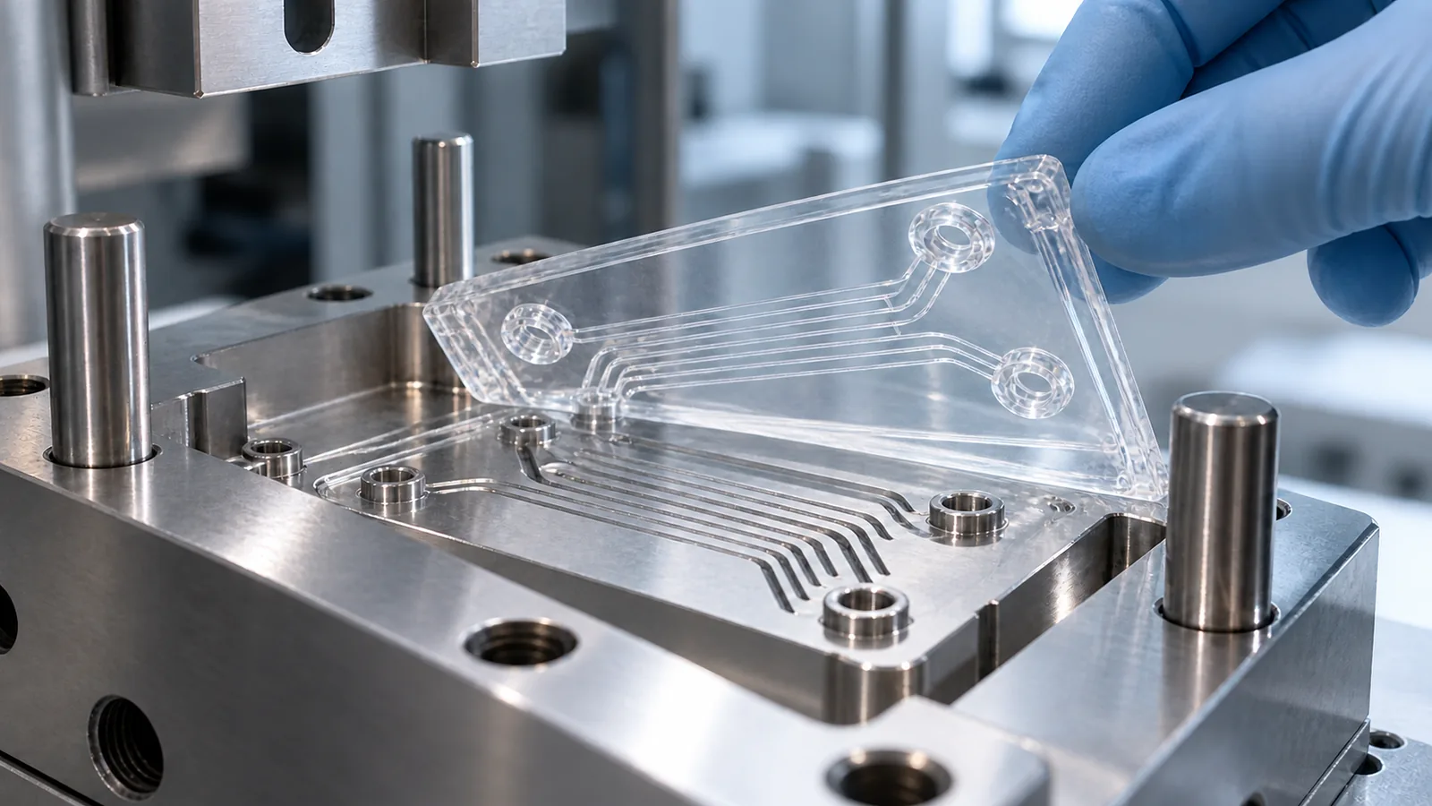
High-aspect-ratio ribs in the mold form narrow channels in the part. During release, friction, insufficient draft, roughness, vacuum, or early ejection can pull on the channel walls and edges. The damage may appear as taper, whitening, drag lines, or a localized profile change.
Tool finish should support both replication and release. Highly polished surfaces may be required for optics, and an optical and clear molding review can align surface finish, gate placement, stress control, and inspection. Texture direction and contact length still influence friction. Ejection should load supported nonfunctional areas and keep the part flat until it is safely transferred.
Compare in-cavity expectations with post-ejection measurements. If the profile changes after release or conditioning, the correction belongs in cooling, draft, surface, ejection, or handling—not automatically in filling.
Control Particles Before They Become Flow Restrictions
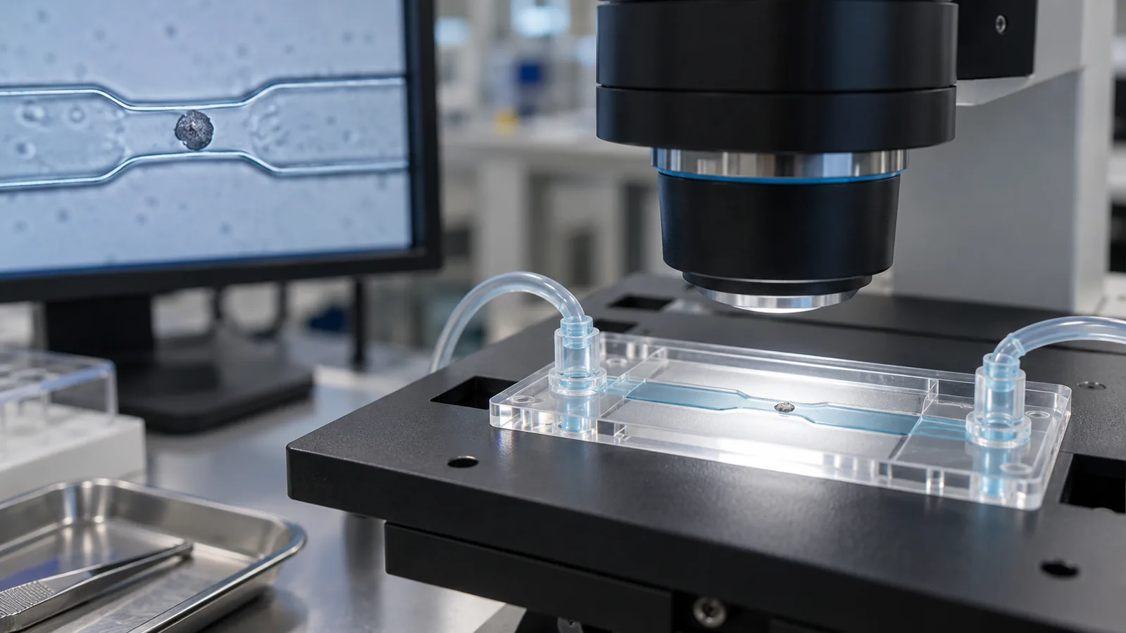
Particles, fibers, degraded resin, mold deposits, release agents, and handling residue can obstruct channels or interfere with bonding. Clean appearance at normal viewing distance is not enough when a small particle occupies a meaningful fraction of the flow path.
Define the required cleanliness level from the device risk and downstream process. Material handling, tool cleaning, air quality, operator contact, packaging, and transport should support that requirement. Avoid adding mold release unless its effect on bonding and fluid contact has been validated.
Traceability is useful when contamination is intermittent. Record cavity, shot sequence, material lot, cleaning event, and packaging batch so a particle finding can be investigated rather than treated as random.
Validate the Finished Fluidic Device
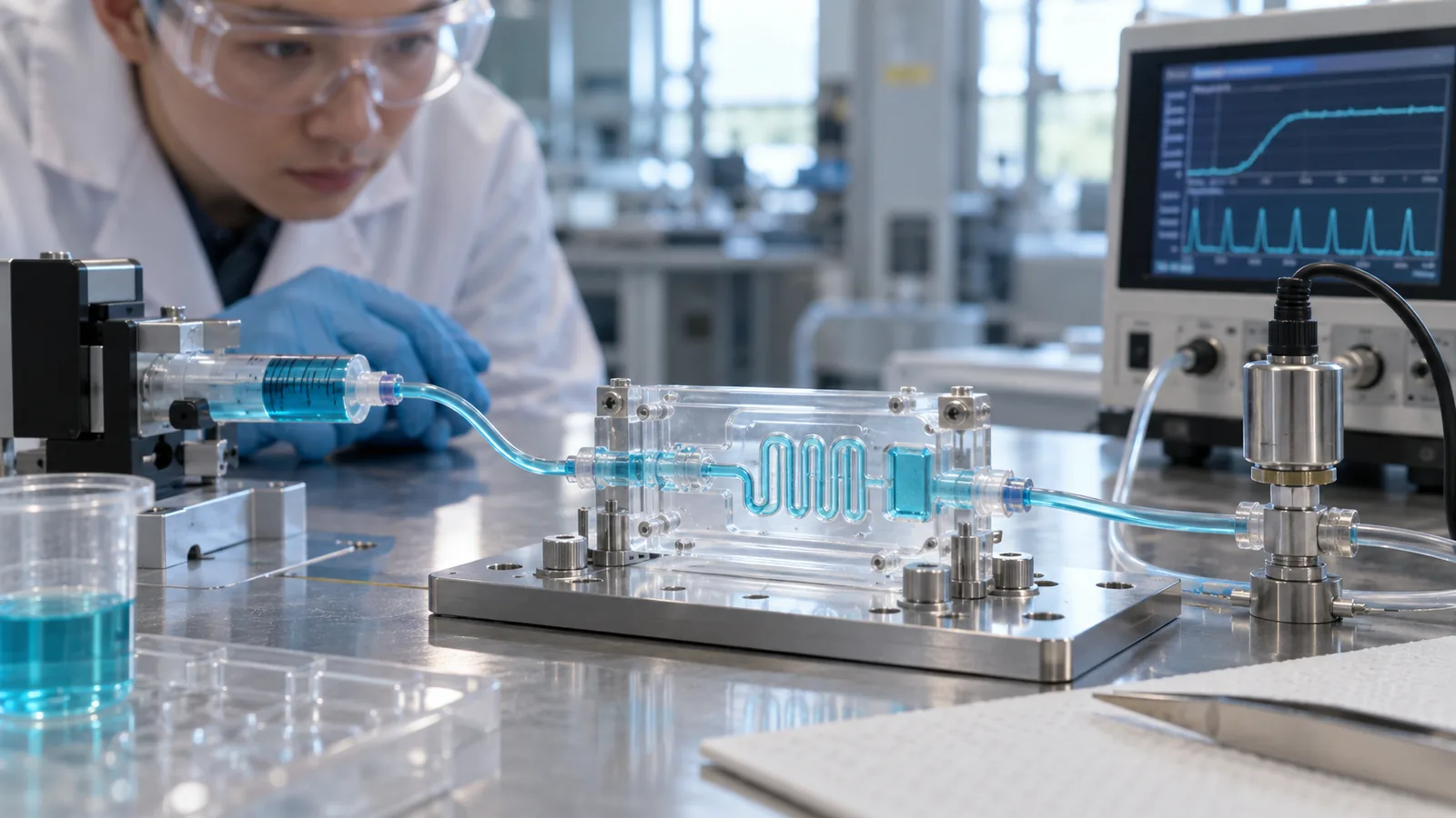
Dimensional inspection is necessary but not sufficient. Seal the part using the intended process, then test leakage, burst or pressure behavior where relevant, flow rate or hydraulic resistance, mixing, optical detection, and chemical compatibility. Bonding can squeeze channel roofs, add residue, or introduce stress that was absent after molding.
- Measure critical channel profiles before bonding.
- Record bond temperature, pressure, energy, time, and alignment.
- Section or image representative sealed channels.
- Run functional fluid tests across cavities and lots.
- Challenge the expected storage and use environment.
- Correlate functional results with molded and bonded dimensions.
For diagnostic and medical uses, the broader medical injection molding plan may also need contamination, traceability, packaging, and validation controls. The Микролитъе под давлением link in that chain is only one stage of the finished device.
Часто задаваемые вопросы

Why can two channels with the same width flow differently?
Depth, corner shape, roughness, taper, roof deformation, particles, and fluid properties can all change resistance. Width alone does not define the profile.
Does a higher mold temperature improve every channel?
It can delay surface freeze and improve replication, but it may also affect cycle time, release, stress, and dimensions. The safe process window must be validated.
When should channels be measured?
Measure after molding and again after the intended bonding and conditioning steps. The finished device state governs function.
Can optical clarity be judged visually?
Visual inspection is useful for gross defects, but detection applications should be tested at the relevant wavelength and geometry.
What should a microfluidic RFQ include?
Include channel CAD, functional tolerances, fluid and pressure, optical method, material restrictions, bonding route, cleanliness needs, test plan, and volume.