
A fabricação de hardware de precisão depende fortemente da fabricação de ferramental de alta integridade.
A transição de conceitos de produtos personalizados de desenhos de engenharia 2D para a produção em volume exige um projeto meticuloso de cavidades e fresamento CNC de alta velocidade.
Fornecer serviços fabricação de moldes personalizados especializados exige a usinagem interna de núcleos de moldes e estruturas principais para eliminar atrasos na cadeia de suprimentos de terceiros.
Operar como um fabricante contratado integrado garante controle de qualidade completo, desde o corte inicial do aço ferramenta até a injeção de componentes em massa.
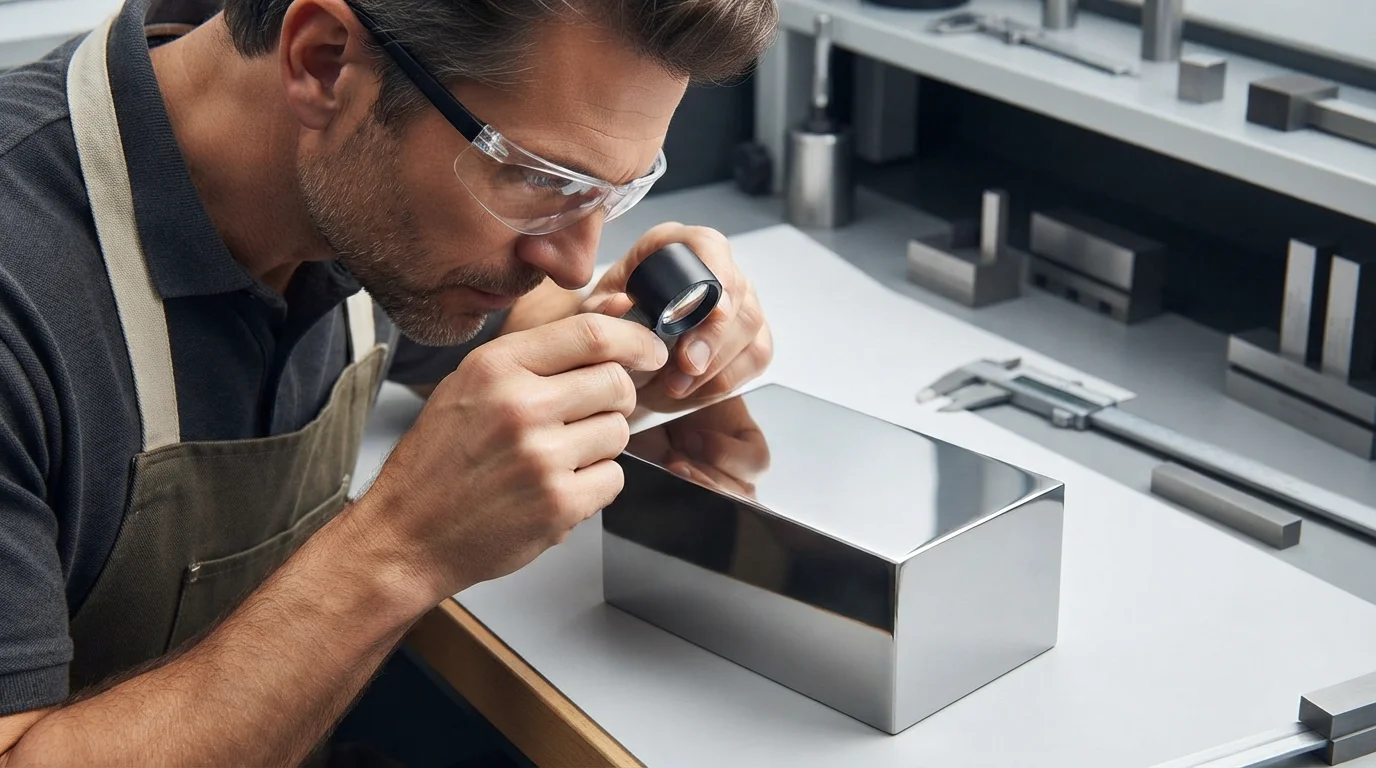
O ferramental contratado concentra-se exclusivamente em estruturas de moldes personalizadas em 100%, evitando ferramental de catálogo pronto para uso.
Operar uma sala de ferramentas interna verticalmente ao lado do departamento de moldagem permite que engenheiros de ferramental e técnicos de processamento colaborem perfeitamente.
Seja construindo ferramental rápido de alumínio para validação de protótipos ou construindo moldes de produção de aço inoxidável endurecido, as equipes de engenharia devem garantir a geometria exata das peças e a confiabilidade do ferramental a longo prazo.
Índice
25 Centros de Usinagem CNC de Cinco Eixos e Tolerância de Ferramental de ±0,01 mm
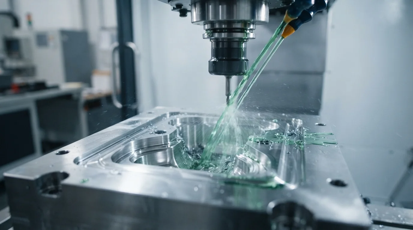
A precisão do ferramental é respaldada por 25 conjuntos de máquinas CNC de 5 eixos, cortadores EDM de penetração de alta velocidade e unidades de EDM a fio.
A fresagem CNC de cinco eixos permite cortar contornos 3D complexos, cavidades profundas de núcleo e nervuras internas intrincadas em uma única configuração.
Eliminar múltiplas fixações da peça de trabalho minimiza erros cumulativos de posicionamento, mantendo tolerâncias de fabricação de moldes de ±0,01 mm e repetibilidade da peça de ±0,02 mm.
Equipar a sala de ferramentas com cortadores de alta velocidade operando a 20.000 RPM proporciona acabamentos superficiais impecáveis diretamente da máquina.
A usinagem de precisão se estende à fabricação automatizada de eletrodos para corte de núcleo por EDM, permitindo cantos internos nítidos e nervuras de raio apertado.
Manter estabilidade térmica rigorosa em oficinas de usinagem com clima controlado evita erros de expansão térmica durante longas operações de fresagem.
A fabricação interna de moldes personalizados elimina riscos na cadeia de suprimentos de terceiros e preserva total confidencialidade da propriedade intelectual.
Controlar cada etapa do ciclo de vida do ferramental permite aos engenheiros realizar modificações ou manutenção imediatas, garantindo cronogramas de produção ininterruptos.
Ferramentas de Aço Endurecido SPI Classe 101 (S136 e H13)
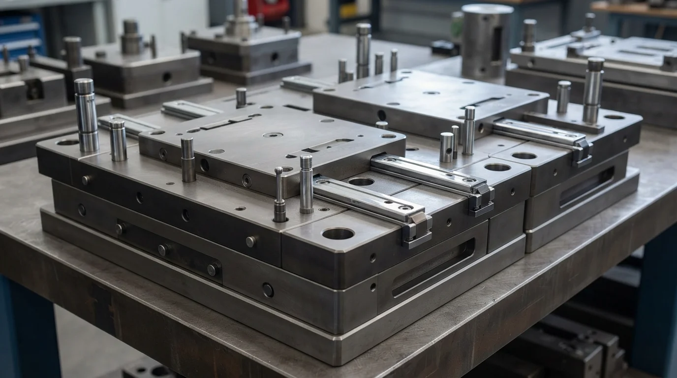
Selecionar o aço ferramenta adequado determina a longevidade do molde, a eficiência de resfriamento e a resistência à desgaseificação corrosiva do plástico.
Especificar aços endurecidos premium, como S136 e aço para ferramentas H13, tratados termicamente a HRC 48-52, fornece bases de moldes de alta resistência à tração.
O aço S136 de alto cromo oferece resistência superior à corrosão contra gases retardantes de chama liberados por polímeros de engenharia como PEEK, Ultem e PPS.
Construção Moldes SPI Classe 101 garante uma vida útil de produção superior a 1.000.000 de ciclos de moldagem.
O ferramental Classe 101 incorpora placas ejetoras guiadas endurecidas, conjuntos de deslizamento resistentes ao desgaste e pinos de núcleo revestidos.
Projetos de aço de corte de precisão evitam a formação de rebarbas de plástico ao longo das linhas de separação ou juntas deslizantes, preservando a estética da peça.
Redes de resfriamento integradas são projetadas usando modelagem térmica avançada para garantir extração uniforme de calor em todas as superfícies da cavidade.
O posicionamento adequado dos canais de água evita pontos quentes no núcleo, reduzindo os tempos de ciclo e eliminando a deformação pós-moldagem em grandes componentes estruturais.
Revisão DfM e Simulação Moldflow em até 24 Horas
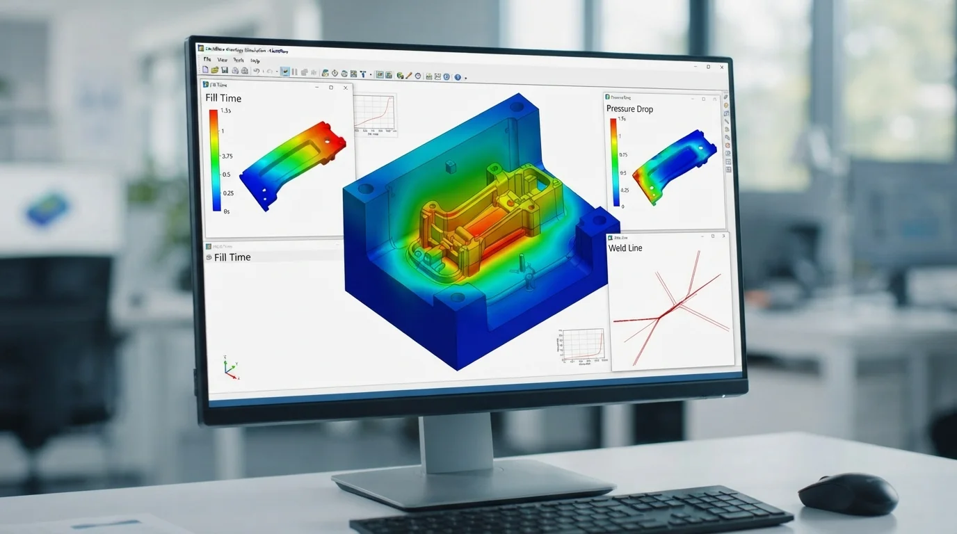
As revisões de engenharia começam com um relatório abrangente de Design para Manufaturabilidade (DfM) entregue em até 24 horas após o envio do arquivo CAD.
As equipes técnicas analisam a uniformidade da espessura da parede, ângulos de saída, localizações de injeção e posicionamentos da linha de separação.
Identificar riscos potenciais de fabricação antecipadamente evita modificações caras no aço após o início da fabricação do molde.
Avançado Simulação Moldflow softwares modelam a reologia de polímeros, as pressões de empacotamento e o comportamento de resfriamento térmico dentro da cavidade.
A simulação da progressão da frente de fusão destaca possíveis armadilhas de ar, marcas de afundamento e formações de linhas de solda.
Ajustar as localizações dos gates com base nos dados de simulação garante orientação ideal das fibras em polímeros reforçados, maximizando a resistência à tração da peça.
Colaborar diretamente com as equipes de engenharia do cliente estabelece dimensões críticas para a qualidade (CTQ) claras e protocolos de inspeção antes do corte do metal.
Essa abordagem proativa de engenharia agiliza a validação, garantindo uma transição tranquila para a moldagem em série.
Ferramental de Ponte Rápida vs. Ferramental de Produção
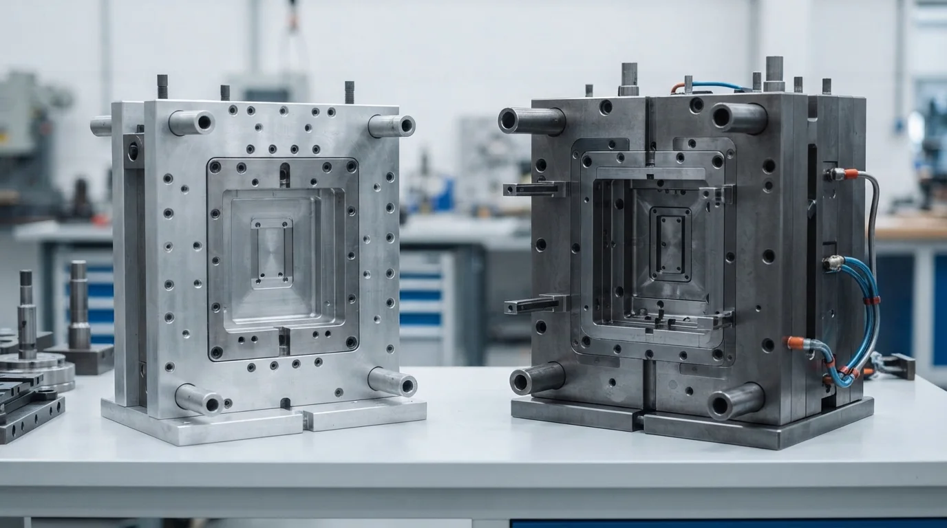
Comparar as opções de ferramental permite que as equipes de desenvolvimento de produto equilibrem os orçamentos iniciais de NRE com os prazos gerais do projeto.
O ferramental de ponte rápida utiliza alumínio de alta resistência Al7075 ou aço macio P20 pré-endurecido para cortar núcleos de molde rapidamente.
A entrega de amostras funcionais de protótipo T1 leva de 7 a 10 dias úteis, ajudando os clientes a validar o ajuste mecânico e realizar testes de campo.
O ferramental de produção utiliza aços para ferramentas S136 ou H13 totalmente endurecidos, projetados para produção contínua em alto volume em mais de 35 prensas de injeção automatizadas, variando de 15T a 3000T.
Enquanto o ferramental rápido é econômico para 1.000 a 10.000 unidades, o ferramental de produção oferece o menor custo unitário para grandes volumes de produção superiores a 100.000 peças.
A execução de fabricação profissional de moldes personalizados garante uma transição perfeita da prototipagem inicial para a produção em massa em larga escala.
Sistemas de gestão da qualidade certificados conforme IATF 16949 e ISO 13485 garantem rastreabilidade completa de documentos e verificação de Inspeção de Primeira Peça (FAI) em cada pedido.
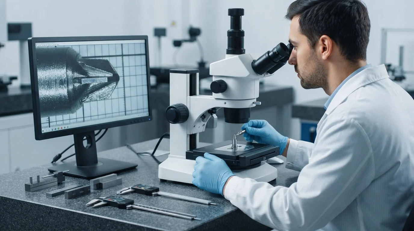
Todo projeto de fabricação de moldes personalizados deve ser verificado com metrologia CMM Zeiss antes de entrar na moldagem em alto volume.
Perguntas Frequentes (FAQs)
Qual é a diferença entre o aço ferramenta S136 e o H13?
O S136 é um aço inoxidável de alto cromo que oferece resistência superior à corrosão e polimento espelhado SPI A-1, ideal para peças médicas e ópticas. O H13 é um aço ferramenta para trabalho a quente ultra resistente que proporciona excepcional resistência ao impacto para peças estruturais e de engenharia de alta temperatura.
Com que rapidez os engenheiros podem receber uma análise DfM para arquivos CAD 3D?
Os engenheiros recebem análises DfM detalhadas dentro de 24 horas após o envio do arquivo CAD. Os relatórios analisam ângulos de saída, espessuras de parede, localizações de injeção e viabilidade da linha de separação.
O que está incluído na garantia de molde SPI Classe 101?
As garantias de molde Classe 101 cobrem manutenção completa do ferramental, substituição de macho e reparo mecânico por mais de 1.000.000 de ciclos de produção. Os moldes apresentam machos de aço temperado, ejeção guiada e tratamentos anticorrosivos.