
A Moldagem de Borracha de Silicone Líquido (LSR) route is often described as a simple two-component injection process. In practice, consistent parts depend on how the material, mold, temperature, and timing are controlled as one system. A small change before the cavity can become a large change in flash, cure state, or dimensional behavior after demolding.
This guide follows the LSR injection molding process in the order an engineering team normally has to make decisions: confirm the material, meter and mix the components, fill a sealed cavity, cure the part, then inspect and release it. The goal is not to provide a universal recipe. LSR grades, part geometry, mold steel, and validation requirements all influence the final window.
Start with a process window, not a single setting
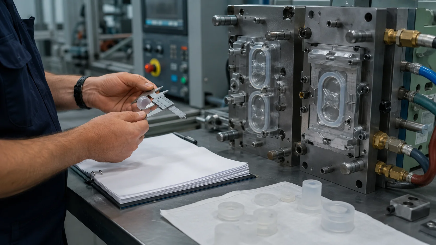
Before tooling trials, define which outputs must remain stable. For a sealing component, compression behavior and flash may matter more than appearance. For a thin flexible membrane, fill completeness and tear resistance may lead the discussion. For a medical or fluid-contact component, traceability, cleanliness, and material documentation must be included from the beginning.
| Control area | What to define early |
|---|---|
| Material | Grade, hardness, cure system, color, shelf life, and lot traceability |
| Ferramentas | Parting line, venting, cold runner, gate, insert retention, and ejection strategy |
| Processo | Metering ratio, fill profile, mold temperature, cure time, and demolding sequence |
| Acceptance | Critical dimensions, visual limits, functional tests, and sampling frequency |
1. Condition and identify the two components
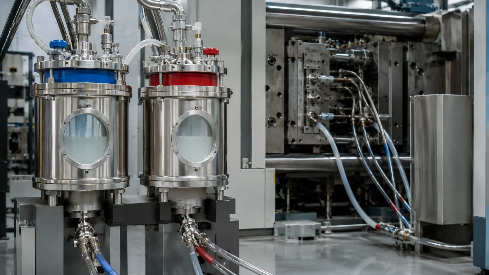
Most injection-grade LSR systems are supplied as separate components that are metered and mixed immediately before injection. Keeping the components isolated prevents premature reaction. The first control is therefore not the mold; it is material handling. Containers should be identified by grade, lot, color system, and expiration or recommended use period. A material change should be treated as a controlled change, not as a routine refill.
The team should also confirm whether the selected grade requires a post-cure, whether it is intended for bonding to a substrate, and whether its documentation matches the end use. Do not substitute a similar-looking silicone without reviewing hardness, cure chemistry, pigment loading, volatile content, and compatibility. These differences can alter flow, adhesion, compression set, and release behavior.
2. Meter, mix, and keep the flow path stable
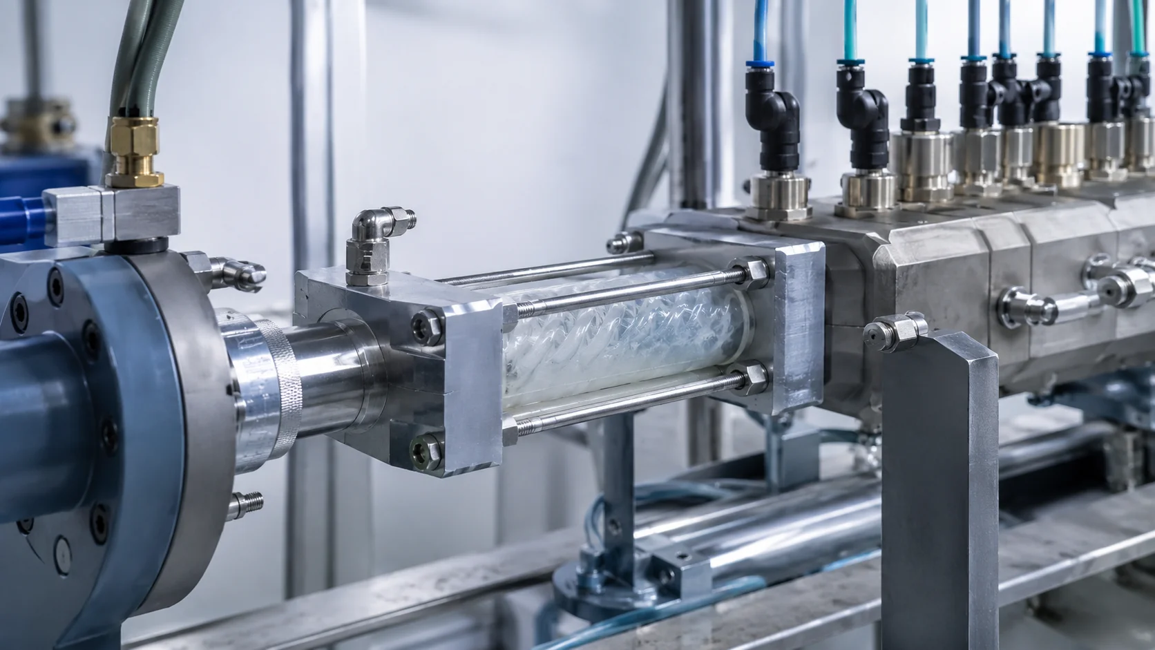
The delivery system brings the two components together at a controlled ratio, mixes them, and sends the mixed material toward the mold. Because the mixed material begins its cure reaction, the path between the mixer and the cavity should be designed to avoid unwanted heat and residence time. A cold-runner layout can reduce waste and improve repeatability, but only when the gates, seals, and temperature zones are balanced for the part.
- Verify ratio: confirm the metering system is delivering the intended component balance.
- Check purge quality: remove unmixed or degraded material before a trial or material change.
- Control residence time: avoid dead zones where mixed material can partially cure.
- Record the lot and setup: connect material identity to the trial and inspection data.
If the process is unstable at this stage, adjusting injection speed alone will not solve the root cause. The symptom may appear as short shots, color variation, bubbles, or an inconsistent cure front, while the actual issue is metering, contamination, or a partially blocked flow path.
3. Fill the heated cavity without trapping air
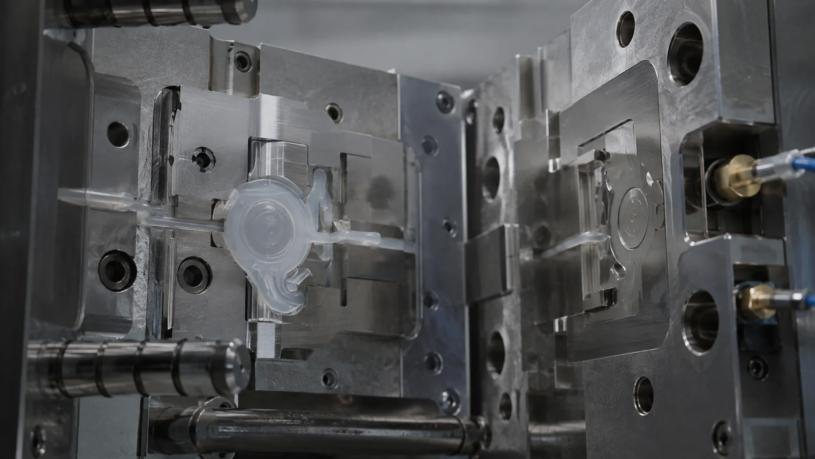
Unlike a conventional thermoplastic process, the LSR cavity is heated to promote curing while the material delivery path is kept comparatively cool. The mold must therefore fill smoothly and vent the air displaced by the advancing flow front. Gate location, wall thickness transitions, weld-line position, and venting are linked decisions. A thin section placed at the end of flow may need a dedicated vent even if the part appears easy to fill in CAD.
Use trial data to separate a filling problem from a venting problem. A short shot that moves when the fill profile changes may be flow-related. A burn mark, trapped bubble, or incomplete knit line near the end of fill may point to insufficient air escape. Mold cleanliness also matters: residue at a parting line can create a leak path for flash and change the apparent filling behavior.
4. Cure the part consistently across the cavity
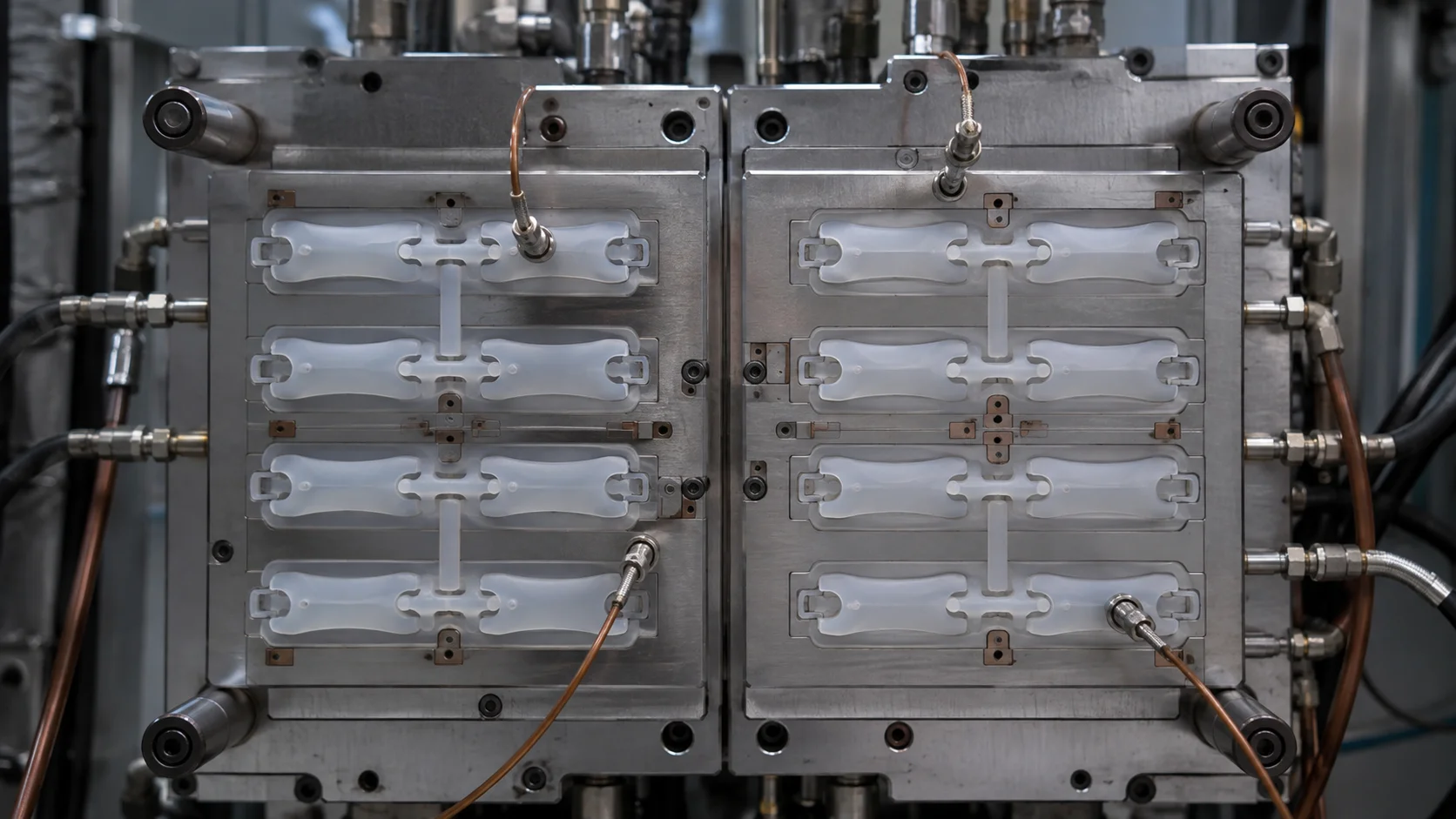
Cure is governed by the interaction of material kinetics, mold temperature, part thickness, and time. A surface can look finished while a thicker region is not fully cured. Conversely, excessive heat exposure can affect color, adhesion, or post-cure behavior. Use representative thermal locations during qualification and define the cure window from part performance, not only from the machine display.
Multi-cavity tools require particular attention to balance. If one cavity fills or cures differently, compare gate condition, venting, thermal contact, and runner resistance. A quality-control plan should connect the measured process variables to a functional result, such as leak testing, compression recovery, pull-off strength, or visual flash limits. Jucheng’s quality-control approach can be used as an internal reference when defining inspection checkpoints, but project-specific acceptance criteria still need customer approval.
5. Demold, inspect, and lock the learning into the next run
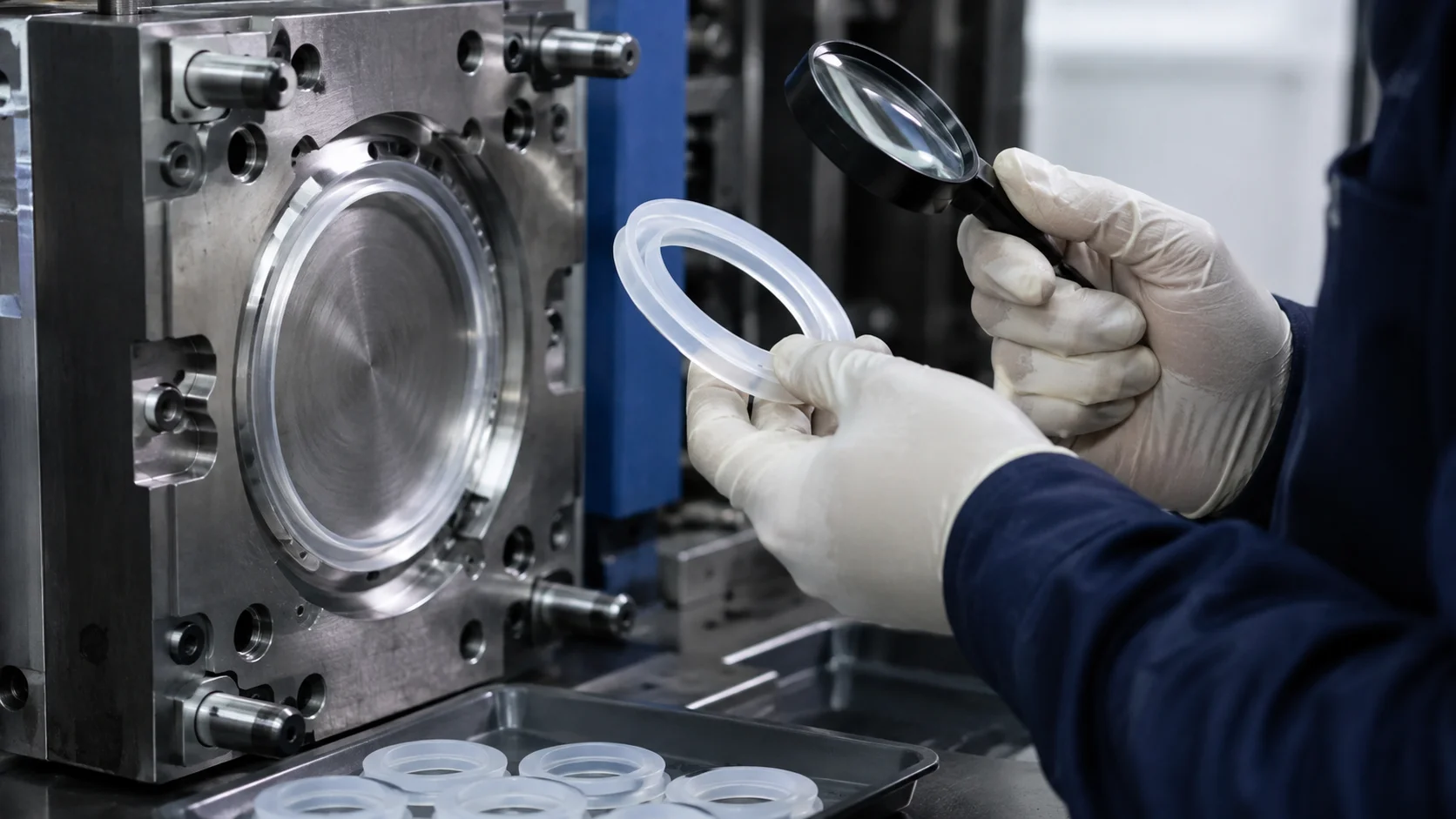
Demolding is part of the process, not an afterthought. LSR parts can be flexible, thin, and easily stretched, so excessive ejection force or an unfavorable parting line can create distortion that is mistaken for a molding defect. Review the release sequence, undercuts, vent land, and any manual handling before changing material or cure settings.
- Inspect flash and parting-line condition before trimming.
- Measure critical dimensions after the defined stabilization time.
- Run the functional test that represents the real use case.
- Document the approved window, not only the nominal value.
A robust LSR process is a controlled chain: verified material, stable metering, balanced filling, repeatable cure, gentle release, and evidence-based inspection. When a project enters tooling review, share the CAD, expected annual volume, critical dimensions, substrate details, and validation needs. This allows the mold concept and process plan to be developed together instead of correcting avoidable problems after the first trial.