
Good light pipe design can still fail after tooling because optical efficiency is only one part of the job. The molded component must also couple to the LED, clear the enclosure, release without damage, hold its alignment, avoid visible gate and ejector marks, and remain stable through assembly. A ray-trace model may predict acceptable output while the production part shows a dim face, bright hot spot or crosstalk. Closing that gap requires the optical, mechanical and molding decisions to share the same datums and acceptance test.
What usually goes wrong
Teams optimize the clear geometry, then treat the gate, parting line, ejectors, retention features and PCB stack-up as secondary details. Those details decide whether the modeled optical path survives molding and assembly.
En este artículo:
- Treat the part as an optical path
- Control the LED interface first
- Give bends and surface features one job
- Keep tooling outside the optical function
- Stop crosstalk before adding LED power
- Validate the assembled system
- Preguntas frecuentes
A Light Pipe Is an Optical Path, Not a Clear Rod
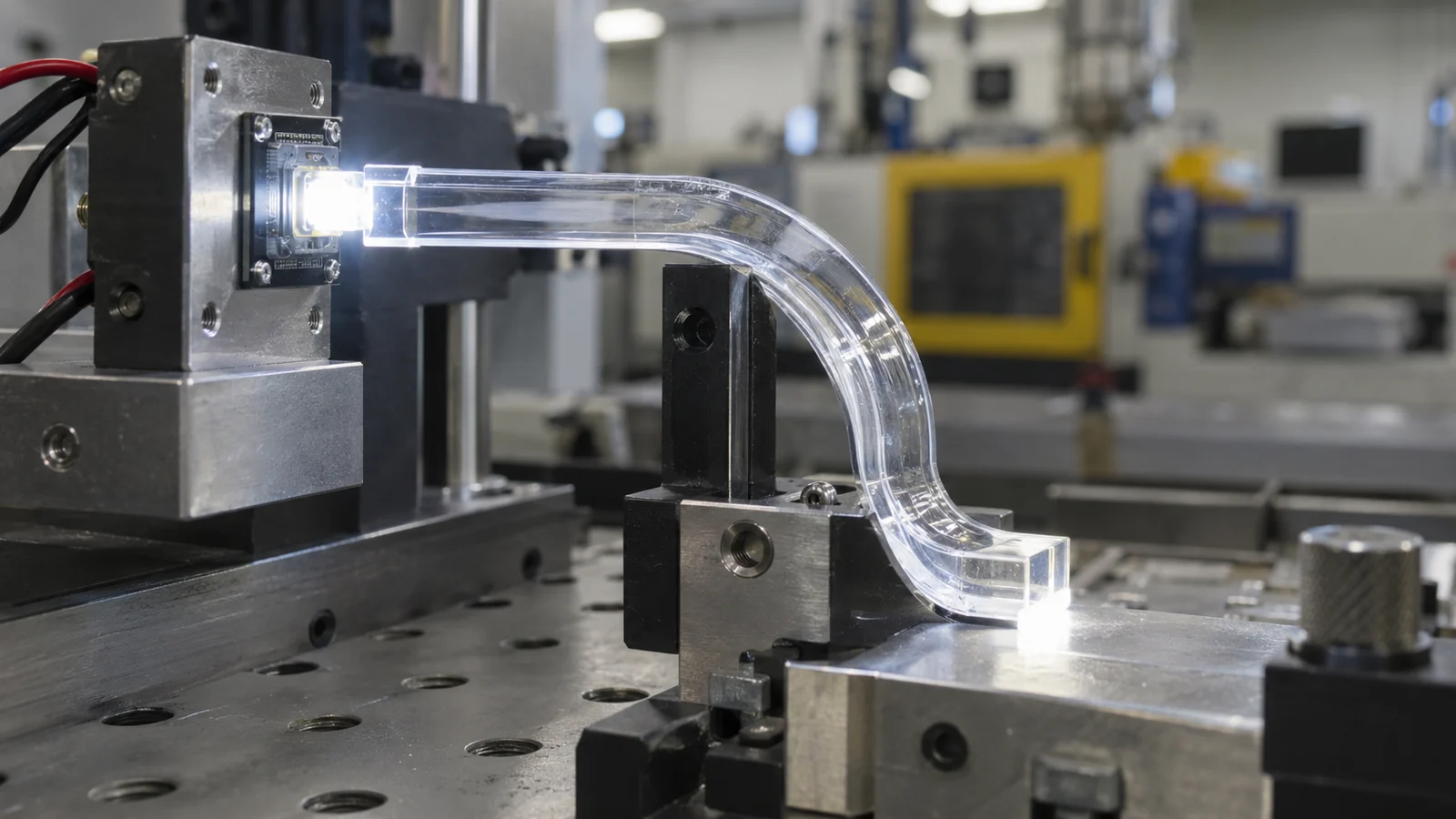
A light pipe carries light from a source to a viewing surface through internal reflection and controlled extraction. Its performance depends on more than transparency. Entry geometry, surface condition, bends, wall contact, mounting features and the exit face all change where light travels and where it escapes.
Start by defining what the observer must see. A status indicator may need a uniform illuminated dot from several viewing angles. A backlit icon may need controlled diffusion. A long edge-lighting feature may need extraction structures that deliberately release light along its length. These are different optical jobs and should not share one generic geometry.
Separate the optical zone from the mechanical support zone on the drawing. The optical zone needs surface and geometry controls tied to light output. The support zone can carry retention, assembly and ejection features. Combining both functions in the same small area often produces compromises that are difficult to diagnose after tooling.
Coupling Loss Starts at the LED Interface
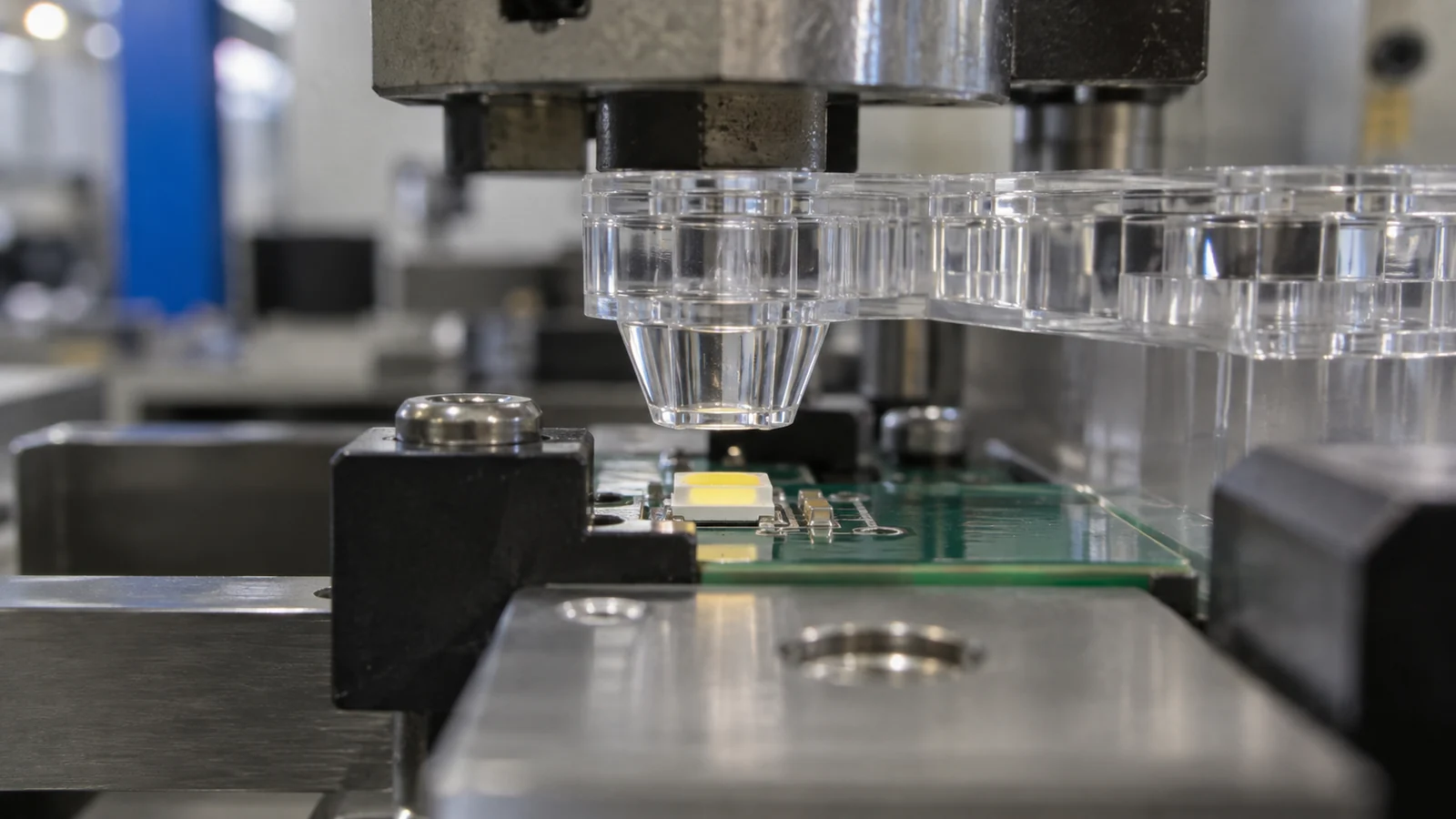
The entrance face cannot collect light that never reaches it. LED package height, emitting area, viewing angle, board tolerance and the air gap between LED and pipe should therefore be treated as one tolerance stack. A nominally centered light pipe can perform poorly when the PCB, enclosure and molded retention features move in opposite directions at their tolerance limits.
Keep the entrance face large enough for the expected source and positional variation, but do not assume that a larger gap is harmless. Gap, angle and surface finish change how much light enters the pipe. A locating feature that references the enclosure while the LED references the PCB can create a hidden datum conflict. The design review should identify which component controls the final optical alignment.
Commercial light-pipe suppliers also pair geometry with particular LED arrangements rather than treating the pipe independently. Dialight’s LED indicator design guidance, for example, begins with layout alignment and source selection. A custom molded design needs the same system-level discipline.
Give Bends and Surface Features One Job
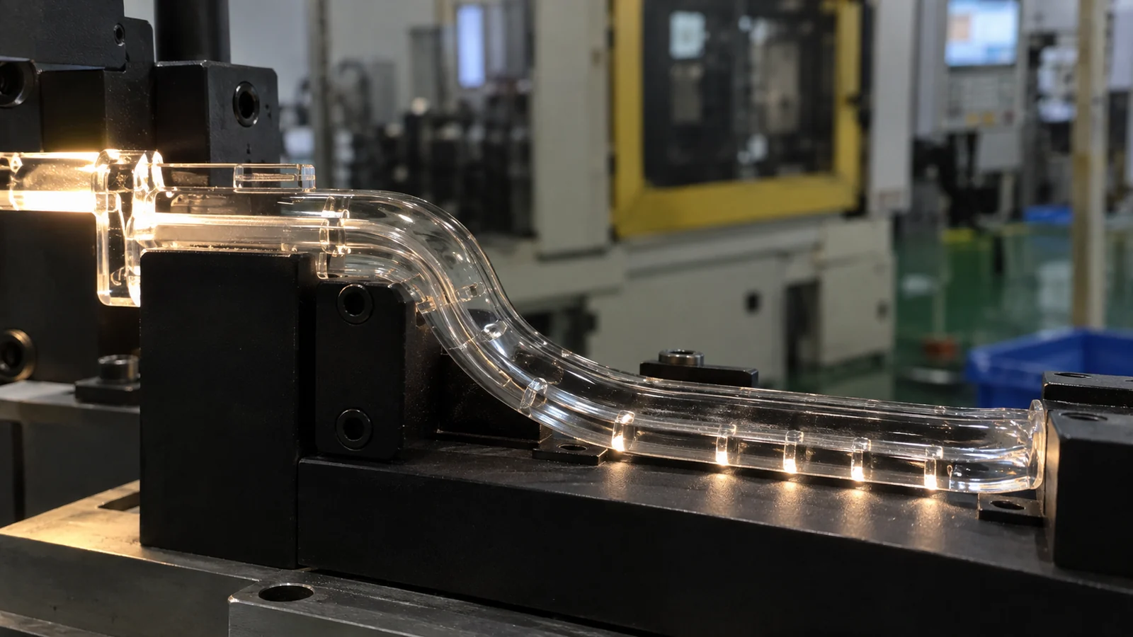
Every bend changes the incidence angles inside the part. A tight turn can let light escape, concentrate brightness on one side or create a visible hot spot. The solution is not always to add a texture. Texture, prism features and diffusing geometry intentionally disrupt the optical path; if they are placed without a defined extraction purpose, they can reduce useful output while only hiding the symptom.
Use smooth, gradual transitions where the design intends to preserve internal reflection. Reserve microfeatures or diffusion for locations where light must leave the pipe. Keep ribs, bosses and snap features away from critical reflection surfaces when possible, because their local thickness and shrinkage can distort the surface that carries the light.
A polished surface is not automatically correct everywhere. Entry and transport surfaces may need smooth replication, while the exit face may need a controlled texture or optical pattern. The drawing should state the function of each surface rather than apply one finish note to the complete component.
Tooling Details Can Undo the Optical Design
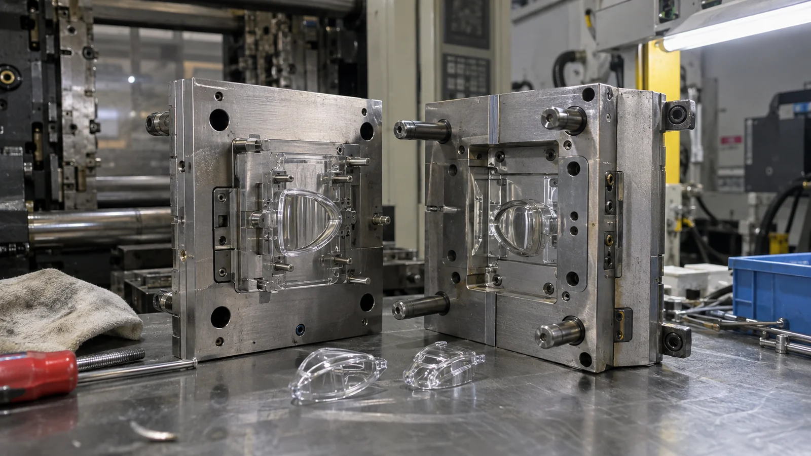
Mold construction determines where the design must accept a parting line, gate vestige, vent witness and ejection contact. Placing any of them inside a critical transport or viewing surface can scatter light or create a visible interruption. Moving them outside the optical zone may require a different draw direction, split or retention concept, so these decisions belong in early DFM—not after the optics are frozen.
Gate position affects more than cosmetics. It sets the flow direction, the highest-shear region and the way packing pressure reaches the part. A restrictive gate beside the light path can leave stress or a visible flow signature. A remote gate may improve appearance but create a longer flow path and weaker packing at the far end. In Moldeo por inyección óptico y transparente, the gate should be reviewed against optical function, flow balance and removal method together.
Ejection is another common blind spot. A long slender pipe can flex during release, while a broad viewing face can show stress or witness marks if ejection force is concentrated. Draft, polish direction and support during ejection must protect both geometry and optical surfaces.
Control Crosstalk Before Adding More LED Power
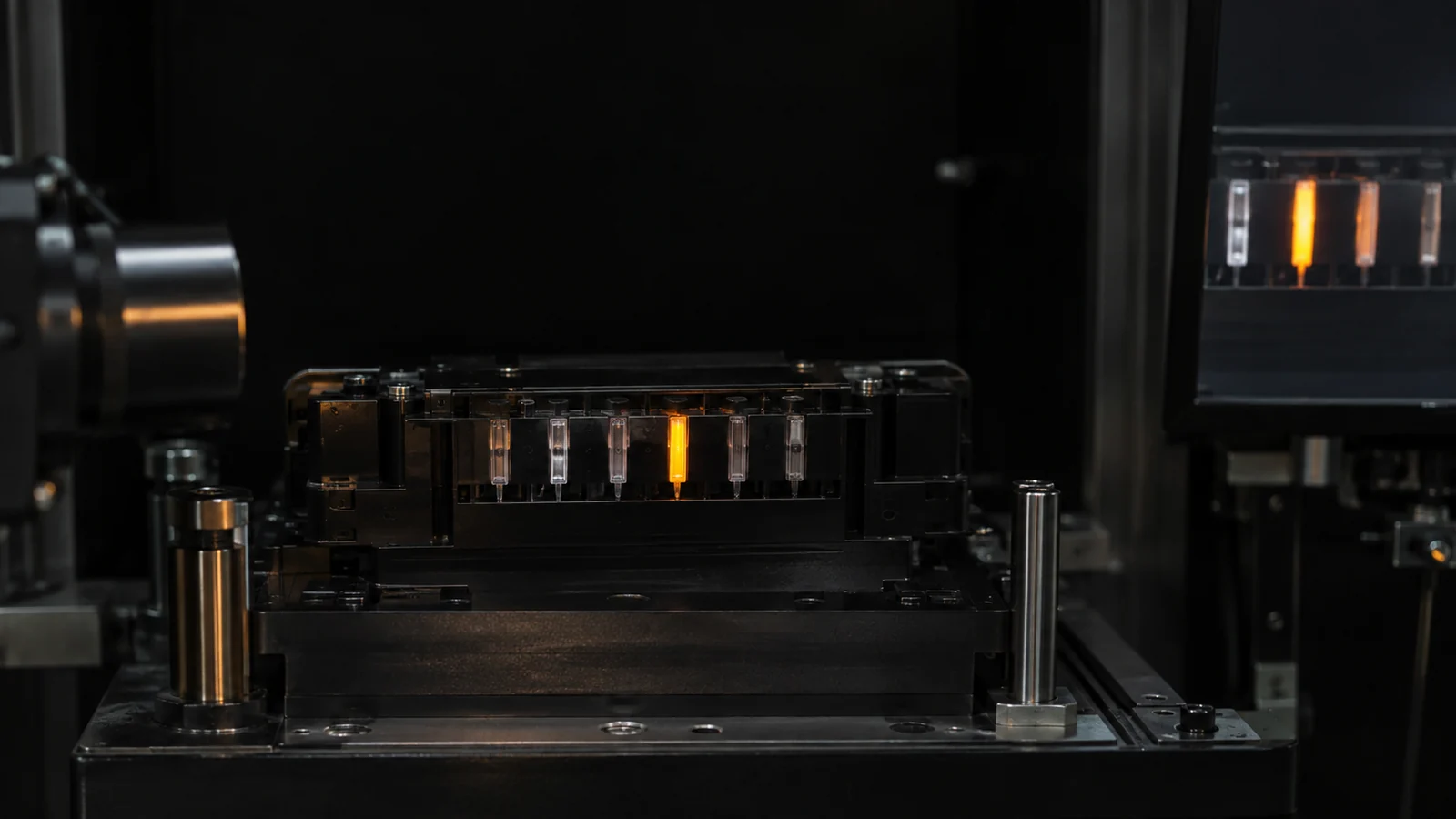
When adjacent indicators glow at the same time, increasing LED output usually makes the crosstalk more obvious. First identify whether light is escaping from the pipe, traveling through the clear mounting structure, reflecting inside the enclosure or entering the neighboring pipe at its source.
Opaque barriers, isolated holders and controlled gaps can block unwanted paths, but they also consume space and add assembly interfaces. A black housing around individual pipes is effective only when the barrier remains continuous after tolerance and assembly variation. Glossy internal walls can reflect light around a nominal barrier; matte dark surfaces may be more useful in those locations.
| Síntoma observado | Evidence to collect | Likely review area |
|---|---|---|
| Bright entry, dim exit | Gap and alignment at LED | Coupling face and datum stack |
| Hot spot after a bend | Brightness map through the turn | Bend radius and surface continuity |
| Neighboring icon glows | One LED powered at a time | Barriers, holder and enclosure reflections |
| Cavity-to-cavity variation | Output by cavity and position | Tool replication, cooling and process balance |
Prototype the System, Not the Isolated Part
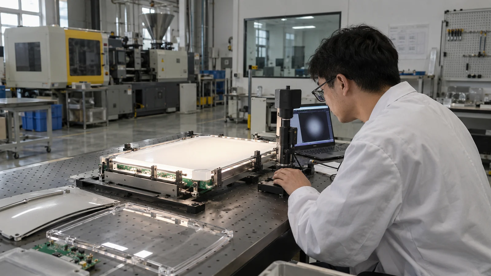
A loose light pipe held above a bench LED does not reproduce the final air gap, alignment, enclosure reflection or observer angle. Validation should use the intended LED, PCB, holder, enclosure and front panel whenever possible. Record both electrical input and optical output so a brighter LED is not mistaken for a better pipe.
Build the acceptance test around the product’s viewing condition. Useful outputs may include luminance at defined angles, uniformity across the exit face, color difference, crosstalk at neighboring indicators and retention after assembly. The exact metric depends on whether the device communicates status, illuminates a symbol or distributes light across a larger feature.
- Lock the LED part number, drive condition and PCB reference.
- Measure the assembled gap and alignment, not only CAD nominal values.
- Test multiple molded cavities and more than one production cycle.
- Inspect the gate, parting line, ejection and handling marks under the same lighting used for approval.
- Recheck performance after enclosure assembly and expected environmental exposure.
Material candidates should be screened at the grade level. Review PMMA optical molding considerations when transmission and weathering lead the decision, or polycarbonate grade requirements when impact and temperature resistance carry more weight.
Preguntas frecuentes
Should a light pipe touch the LED?
Not automatically. The required gap depends on the LED package, entrance geometry, thermal and assembly conditions. The important requirement is a controlled, repeatable interface that remains inside the validated coupling range.
Why does the molded light pipe look dimmer than the prototype?
Check the LED alignment, air gap, molded surface condition, gate-related stress, bend geometry and enclosure losses. A machined or printed prototype may not reproduce the same surface replication, material, internal stress or assembly stack as the molded part.
Can texture improve light-pipe uniformity?
Texture can redistribute or extract light, but it also reduces light remaining in the pipe. Place it only where the optical model and physical test show that controlled extraction is needed.
What information should a light-pipe RFQ include?
Include the 3D part and assembly, LED datasheet and drive condition, PCB and enclosure stack-up, optical viewing requirements, material preference, annual volume, cosmetic zones and the intended optical acceptance test.