
Stress birefringence is evidence that a transparent polymer no longer behaves optically the same in every direction. It can come from flow orientation, uneven packing, nonuniform cooling, forced ejection or assembly load. The colored pattern between crossed polarizers is useful, but it does not identify the cause by itself. Diagnosis depends on when the pattern appears, where it aligns with flow and how it changes after molding.
Read the pattern in time: compare the part immediately after molding, after conditioning, after annealing trials and after assembly. Changes between those states separate frozen flow orientation from thermal and mechanical loading.
En este artículo:
- Understand what the colors mean
- Map pattern to process history
- Separate molding from assembly stress
- Reduce the correct source
- Write a usable acceptance method
- Preguntas frecuentes
What the Polarized Colors Actually Show
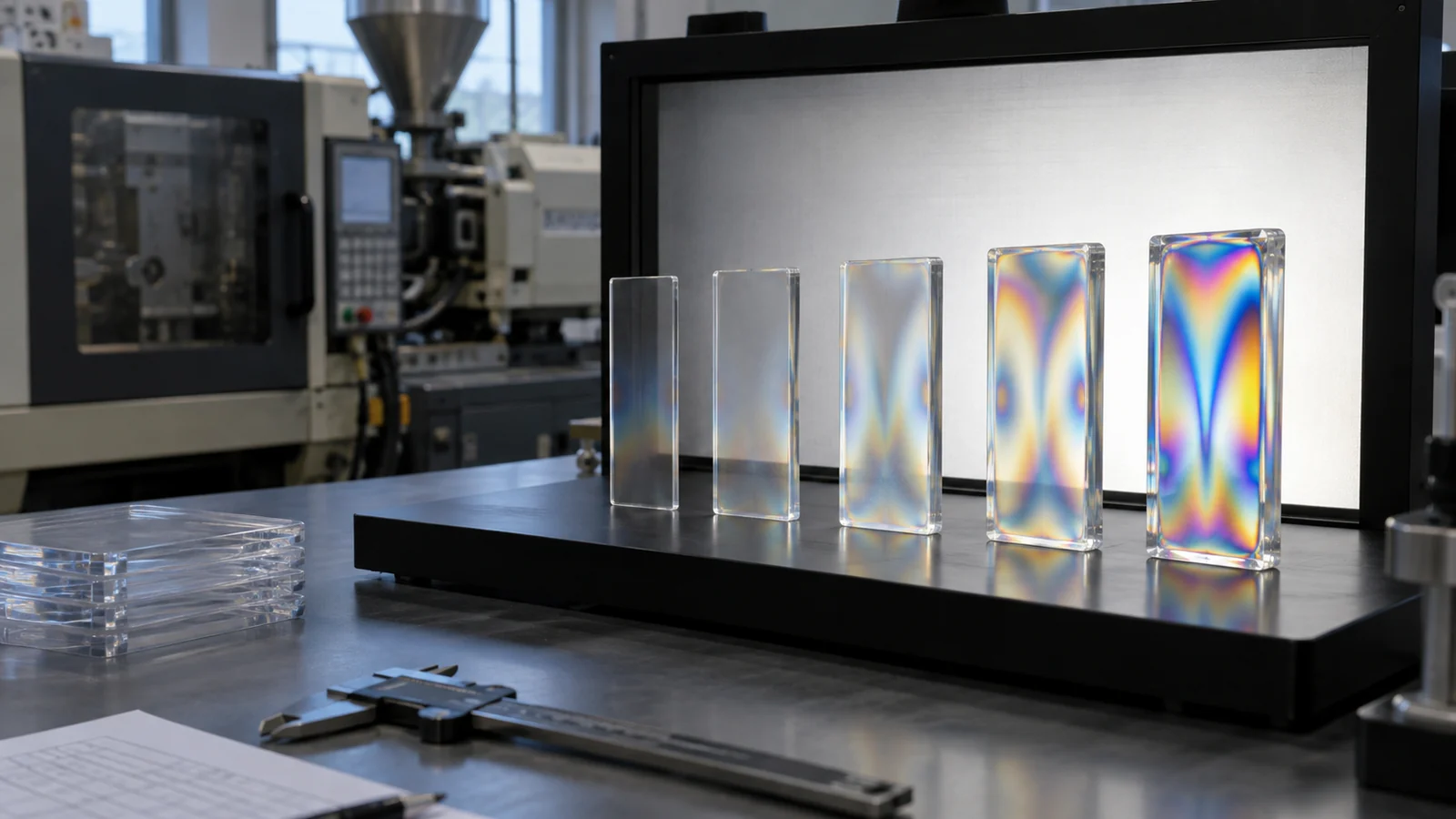
In an unstressed isotropic material, light sees essentially the same refractive behavior in different directions. Orientation and stress create directional differences. Between crossed polarizers, those differences appear as brightness and color related to optical retardation, part thickness and wavelength.
That is why a bright color cannot be converted into a universal stress value without a defined method and material relationship. A thicker region may display a stronger pattern than a thin region under a similar stress state. Use polariscopy to compare like geometry under like conditions.
Map the Pattern Back to Flow and Cooling
A concentrated pattern near the gate can indicate high shear or strong packing. Bands following the flow direction may reflect frozen orientation. A line where flow fronts meet points to weld-line history. Edge patterns can come from rapid skin cooling, overpacking or constraint against the cavity.
Compare short shots to the final part so the pattern has a filling history. Separate cavities and record melt temperature, mold temperature, fill profile, transfer position, hold pressure and cooling time. Without those records, a polarizer image is a photograph of a symptom rather than an engineering control.
Molding Stress and Assembly Stress Can Look Similar
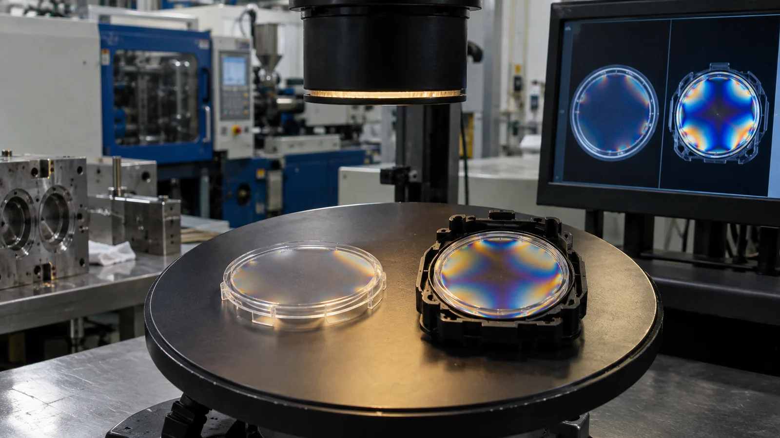
Inspect the loose part first, then repeat after clips, screws, adhesive cure or press fitting. If a new pattern appears near a retention point, the assembly is loading the optic. A molded-in pattern that remains in the same location across assemblies points back toward gate, pack, cooling or ejection.
Time matters. A warm part may relax or distort after ejection. Hygroscopic polymers can also change dimension and stress state during conditioning. Establish a fixed interval and environment before comparing samples.
Reduce the Source Instead of Hiding the Color
If gate shear dominates, compare a less restrictive entry or a fill profile that avoids unnecessary acceleration. If overpacking dominates, confirm gate freeze and reduce pressure after volumetric fill. If cooling is asymmetric, correct water flow, insert contact or steel temperature. If ejection bends the part, improve draft and distribute release force.
Annealing may reduce some residual stress, but it adds time and can change dimensions. It should not become a routine substitute for an unstable mold or process. Within Moldeo por inyección óptico y transparente, the preferred control is a stable process that keeps retardation below the product’s functional limit before secondary treatment.
A Stress Specification Needs a Test Configuration
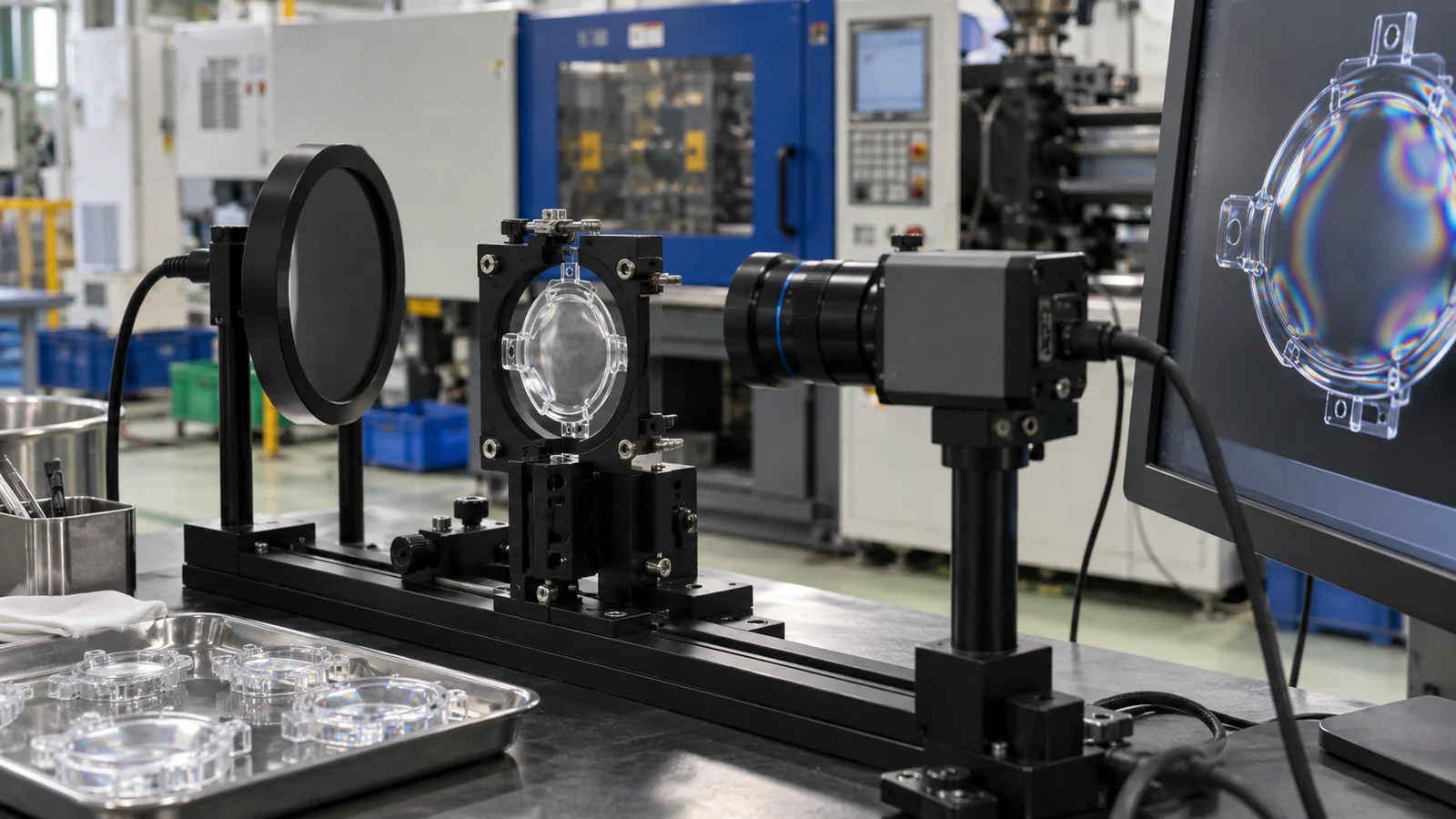
State the polarizer arrangement, wavelength or light source, part orientation, viewing direction, background, camera settings, conditioning and inspection zone. Define whether acceptance uses a reference image, fringe order, retardation value or product-level optical performance.
Tie the criterion to function. A decorative clear cover may accept patterns that would disturb a polarized display, sensor or imaging system. The same molded appearance does not create the same product risk.
Correlate the screen with product performance
During qualification, test parts spanning low, medium and high polarized-light response in the actual optical assembly. That correlation shows whether the screening limit protects the product or merely produces attractive images. Retain boundary samples under controlled storage and repeat the correlation after material or tooling changes.
When requesting a molding review, supply the resin grade, thickness map, gate location, polarizer configuration, assembly torque or interference and the optical symptom. A single colorful photograph without this context rarely distinguishes flow orientation from later mechanical stress.
Use process changes as controlled experiments
When testing a correction, change one mechanism at a time and compare the same cavity. A slower fill, warmer mold and lower pack applied together may improve the image but do not reveal which control matters. Single-factor confirmation creates a setting that can be monitored and recovered later.
Check for tradeoffs after the stress pattern improves. Lower packing may increase sink or dimensional variation; longer cooling may improve release but extend cost; higher temperature may improve replication while increasing residence risk. The accepted process must satisfy optical, dimensional and production requirements together.
Preguntas frecuentes

Does birefringence mean the part will crack?
Not necessarily. It shows optical anisotropy associated with orientation or stress. Crack risk also depends on material, stress magnitude, notches, chemicals, temperature and time.
Can lower injection speed remove it?
Sometimes, but a slower fill can create a colder flow front and other defects. Evaluate speed together with melt and mold temperature, gate design and pressure transfer.
Why does the pattern change after assembly?
Clips, screws, interference, adhesive shrinkage or housing warp can impose new stress. Inspect both loose and assembled conditions.