
A molded lens can meet its diameter and center-thickness dimensions and still miss its optical target. In lens injection molding, form error, decenter, surface replication, residual stress and assembly load all influence the final beam. The practical question is therefore not simply whether plastic can reproduce the CAD model, but whether the molded and assembled lens keeps the required optical function across cavities, lots and environmental conditions.
Short answer
Yes, a molded lens can hold a demanding optical drawing—but only when the optical specification is translated into measurable mold, process and assembly controls. A general dimensional tolerance does not control wavefront, focal shift or transmitted image quality by itself.
في هذه المقالة:
- Translate optical requirements into manufacturing controls
- Select material by the service environment
- Allow for shrinkage and form error
- Protect the optical surface in the mold
- Include assembly in the optical tolerance stack
- Validate function, not appearance alone
- الأسئلة الشائعة
An Optical Drawing Needs More Than Diameter and Thickness
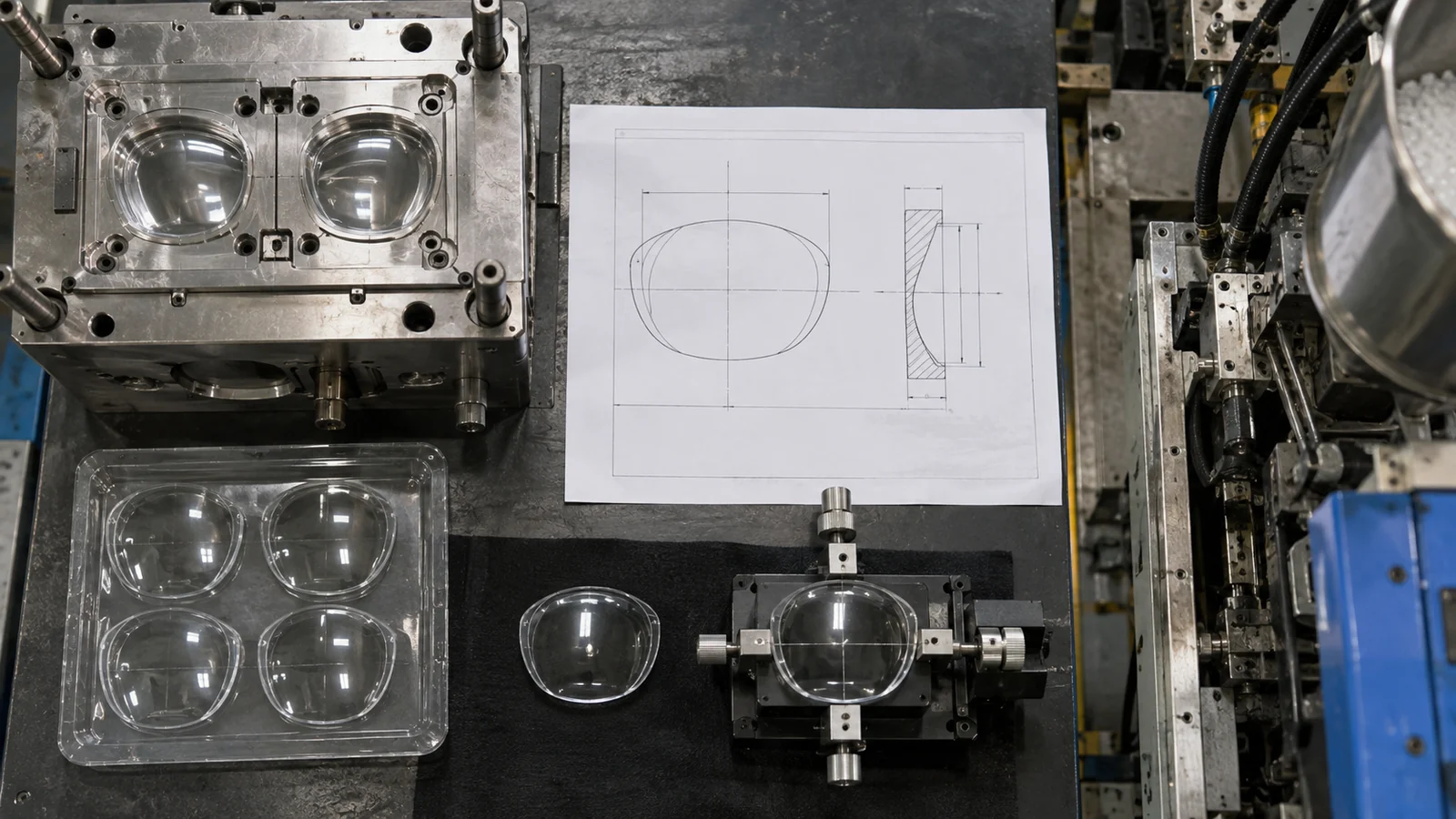
Begin with the function that can fail. A collimating lens may be sensitive to focal length and surface form. An imaging lens may also require control of wavefront error, modulation transfer and centering. A light-distribution optic may be judged by intensity at specified angles. These outputs require different inspection methods, even when the parts look similar.
The drawing should distinguish optical surfaces from mounting and cosmetic surfaces. It should identify optical axis datums, clear aperture, allowable edge conditions and the relationship between the lens and its locating features. If the optical axis is not tied to a measurable mechanical datum, assembly inspection cannot reliably confirm alignment.
Avoid assigning the tightest possible tolerance to every feature. That increases tooling and inspection effort without necessarily improving the beam. Instead, connect each critical requirement to an optical effect and define how it will be measured.
Material Choice Begins With the Failure Environment
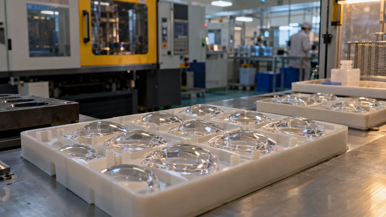
PMMA can offer high clarity and good surface hardness, while optical polycarbonate is often considered where impact resistance or elevated service temperature matters. That comparison is only a starting point. The exact grade, wavelength range, UV exposure, cleaning chemicals, moisture, coating and regulatory requirements can change the decision.
Material also changes the manufacturing window. Melt temperature, mold temperature, drying, shrinkage and sensitivity to stress affect replication and consistency. When reviewing an القولبة بالحقن البصرية والشفافة project, specify the complete resin grade rather than only “PC” or “acrylic.” A grade substitution can alter refractive index, transmission, shrinkage and coating adhesion.
The Steel Surface Is Not the Final Lens Surface
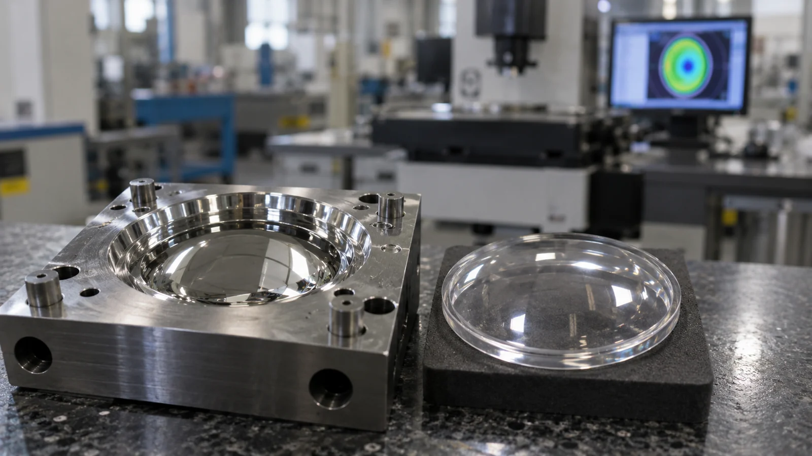
The polymer cools from the mold wall inward. Nonuniform cooling and packing create local shrinkage, which can change curvature and introduce center-to-edge form error. A nominally correct insert may therefore produce a lens that focuses long or short after molding.
Compensation should be based on measured molded parts, not a single generic shrinkage factor. The useful loop is: mold a stable process, measure the lens, compare the optical and dimensional result with the model, then correct the insert only when the deviation is repeatable. Chasing measurements while the process is drifting can put the wrong correction into the steel.
| Observed result | Possible contributor | Check before cutting steel |
|---|---|---|
| Focal shift | Surface form or refractive-index variation | Process stability and full-aperture form data |
| Asymmetric beam | Decenter, tilt or uneven packing | Datum alignment and cavity-specific results |
| Center haze or distortion | Cooling, stress or contamination | Polarized-light pattern and molding record |
Protect the Optical Surface From Gate to Ejection
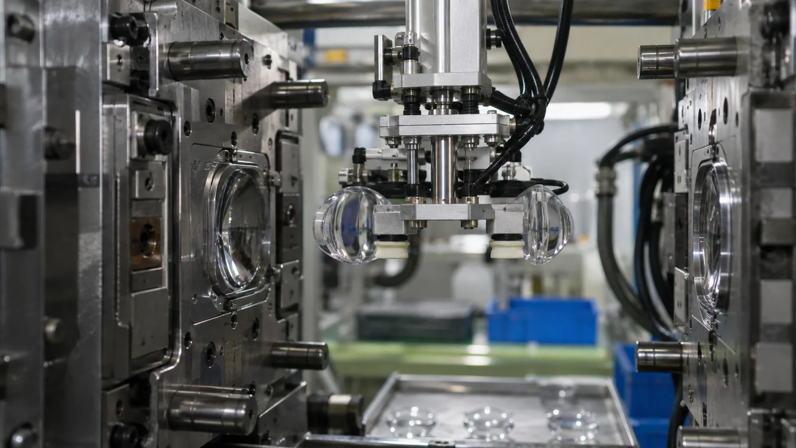
An optical insert must reproduce the required surface without damage from vent deposits, drag or repeated cleaning. The parting line, gate, vents and ejectors should be placed outside the clear aperture whenever geometry allows. A polished cavity is not enough if release force bends the lens or an ejector distorts its locating ring.
Gate location sets the filling pattern and often the residual-stress pattern. Weld lines, hesitation and high shear can appear in the optical path even when the surface is visually clear. Mold-flow analysis can help compare options, but the result still needs a trial plan that measures the actual lens under stable conditions.
Assembly Can Move a Lens That Passed Inspection
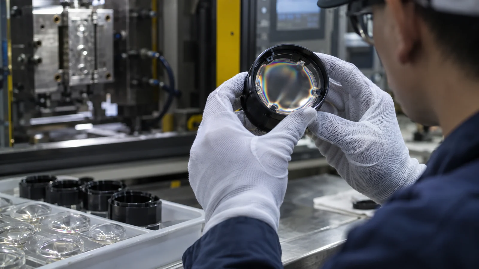
A retaining clip, snap, adhesive bead or screw can load the lens unevenly. That load may tilt the optical axis or create birefringence after the loose part has passed inspection. Mounting features should constrain the necessary degrees of freedom without forcing the optic to conform to a distorted housing.
Review the stack from the optical source or sensor to the lens datum and then to the enclosure. Thermal expansion matters when materials differ and the product sees a wide temperature range. Test the assembled optical module at realistic torque, cure and temperature conditions.
Release the Process With Layered Evidence
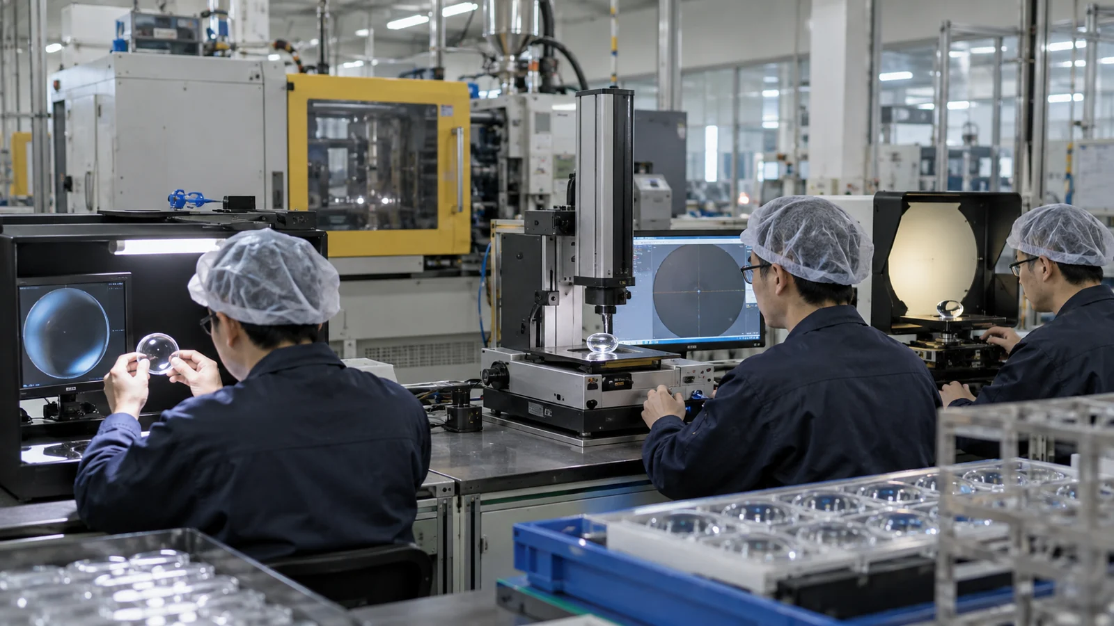
Visual inspection finds scratches, contamination and gross flow defects, but it cannot prove optical performance. Dimensional inspection verifies datums and geometry. Surface metrology evaluates form and finish. Functional testing confirms the beam, image or focal behavior that the customer actually uses.
The sampling plan should separate cavities and track time in the run. Averaging mixed-cavity data can hide one insert that is drifting. Keep process settings, material lot, drying history and measurement conditions with the result so a later change can be traced. The site’s quality-control workflow is most useful when the inspection method is agreed before tooling approval.
الأسئلة الشائعة
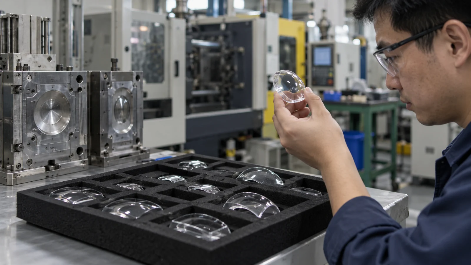
Can injection-molded lenses replace glass?
They can in many products where low mass, integrated features and production volume matter. The decision still depends on wavelength, temperature, chemical exposure, scratch resistance and allowable optical error.
Should every lens receive a functional optical test?
Not necessarily. A capable process may use validated dimensional or metrology proxies plus scheduled functional checks. Safety-critical or extremely sensitive optics may require more extensive screening.
When should insert correction begin?
After the molding process and measurement method are stable and the same directional error repeats across sufficient samples. Correcting steel before that point can compensate for noise rather than the mold.