
Thin-wall LCP parts can look simple in CAD and still be difficult to mold. High flow resistance, fast cooling, tight dimensional requirements, and possible orientation effects make the gate and cavity layout as important as the resin grade. Mold-flow analysis is most useful when it answers a defined tooling question: where the melt will hesitate, where air will remain, and which design change gives the process more margin.
What the Analysis Should Decide
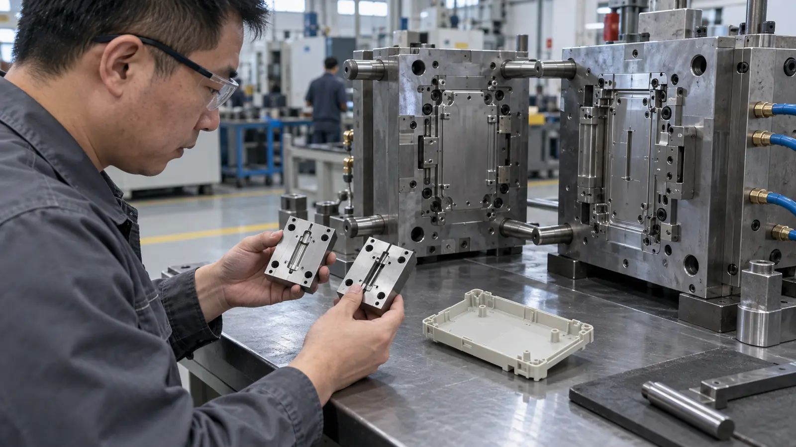
A useful study compares decisions, not just produces colorful plots. For a thin-wall LCP part, the model may compare gate positions, runner balance, fill sequence, weld-line location, pressure demand, or the effect of a local thickness change.
- Can the proposed flow path reach the last-fill region?
- Will the gate freeze before the remote area is adequately packed?
- Where can air traps or burn marks occur?
- Will the flow front create a weld line across a functional feature?
- Does the design leave enough process margin for stable production?
The purpose is to reduce avoidable mold changes. Simulation does not guarantee a perfect part, but it can expose a weak concept while gate and vent decisions are still flexible.
Which Inputs Control the Model
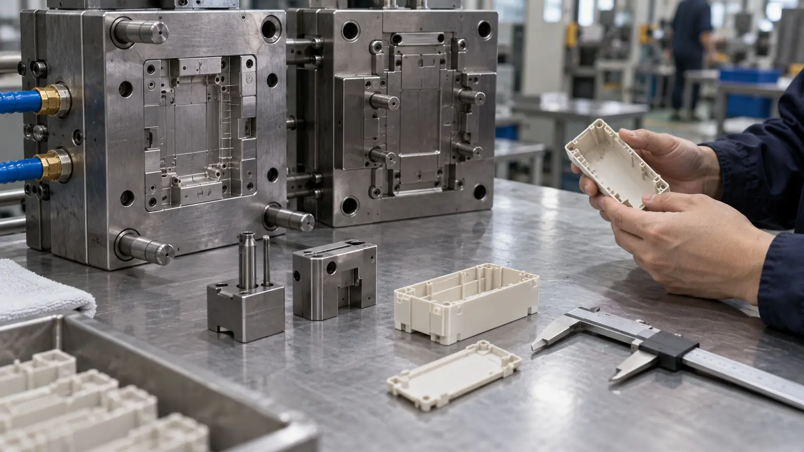
Model quality depends on the input quality. The study should use the intended part geometry, runner and gate concept, material grade, mold-temperature assumptions, and machine limits. Generic resin data can be useful for an early screen, but a material decision should be revisited with supplier data or project-specific validation when the margin is narrow.
| Input | Why it matters |
|---|---|
| Part wall and flow path | Defines resistance, cooling exposure, and end-of-fill behavior. |
| Gate and runner layout | Controls flow direction, pressure loss, balance, and weld-line placement. |
| LCP material data | Influences viscosity, thermal behavior, orientation, and shrinkage predictions. |
| Mold temperature and cooling concept | Changes the frozen layer and the available filling window. |
Which Outputs Deserve Attention
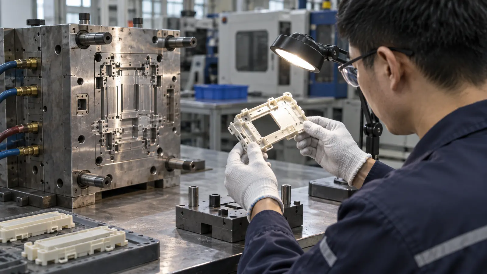
Do not review fill time alone. A part may fill within the predicted time and still show a poor weld-line location, unbalanced pressure, trapped air, or a shrinkage pattern that threatens assembly.
- Fill pattern and last-fill location.
- Pressure demand and available machine margin.
- Air traps, burn-risk areas, and vent locations.
- Weld lines near clips, seals, electrical contacts, or load-bearing features.
- Orientation and anisotropic shrinkage where the design requires tight dimensions.
- Cooling and warpage trends after packing and ejection.
For thin LCP features, the most important output may be the interaction between filling and dimensional behavior. A fast, highly oriented flow can solve a short-shot risk while creating a new flatness or fit problem.
How to Act on the Results
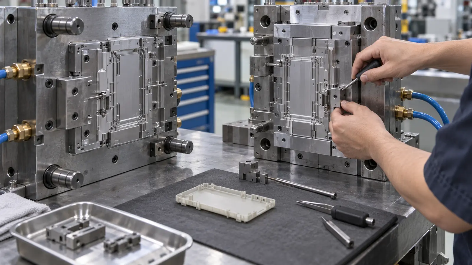
Translate each finding into a design or process action. If pressure is concentrated at the end of a long path, compare a gate move with a material change. If air is trapped behind a rib, review the vent and the feature geometry together. If a weld line crosses a critical feature, move the flow front before trying to hide the mark with a cosmetic adjustment.
The broader 薄壁注塑成型 review should preserve the original decision logic. Keep the model assumptions, alternatives, and chosen changes in the design record so the first molded trial can be compared with the prediction rather than judged from memory.
What Simulation Cannot Replace
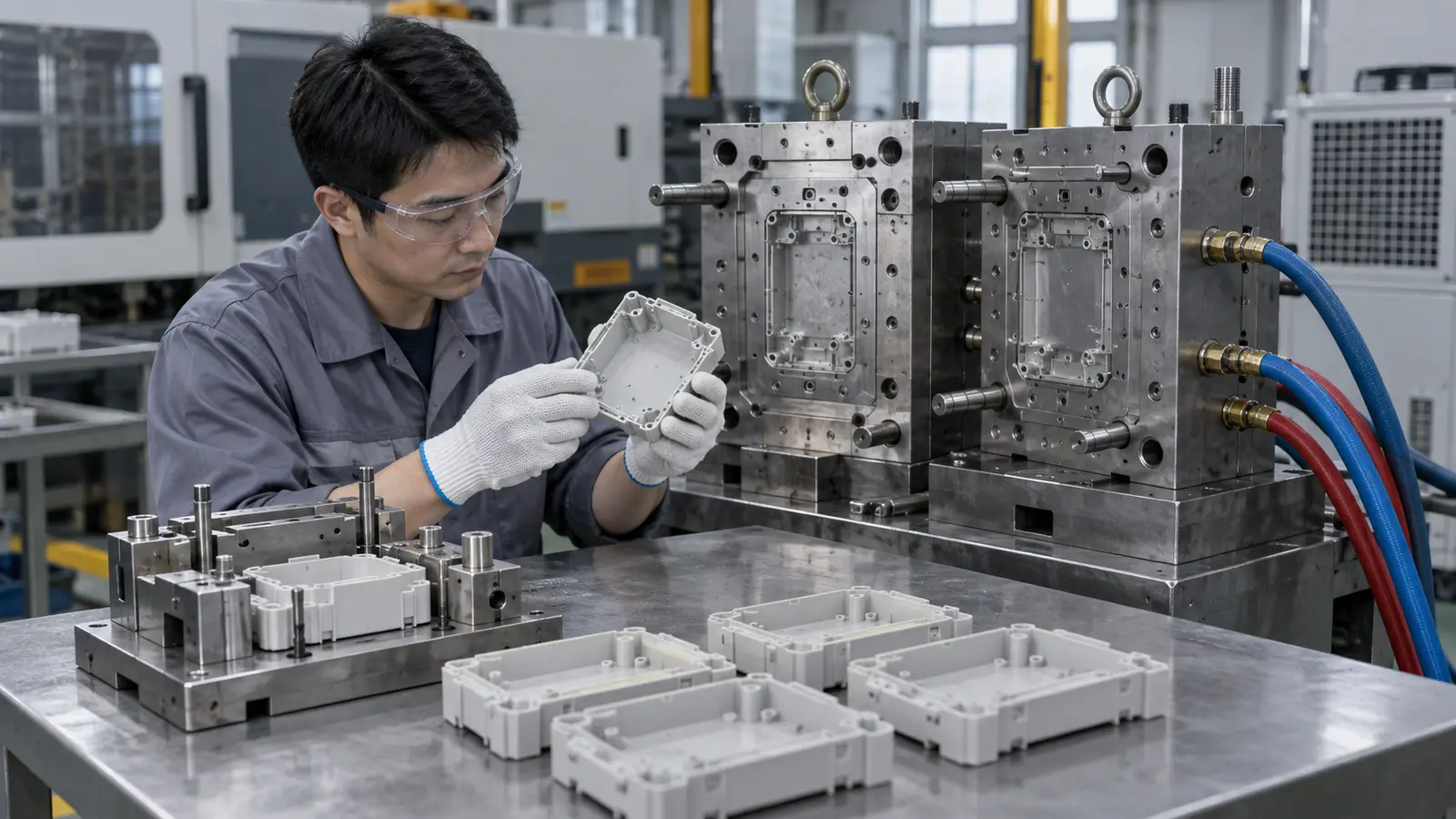
Simulation is an engineering aid, not a substitute for material control, tool workmanship, process setup, or measurement. Real results can shift when the actual resin lot, moisture condition, vent land, steel temperature, or machine response differs from the model.
Use the first trial to validate the important assumptions. Compare fill sequence, pressure behavior, visible weld lines, warpage, and critical dimensions. Differences are useful when they trigger a focused review of the model or the tool.
How to Turn Mold-Flow Results Into a Trial Plan
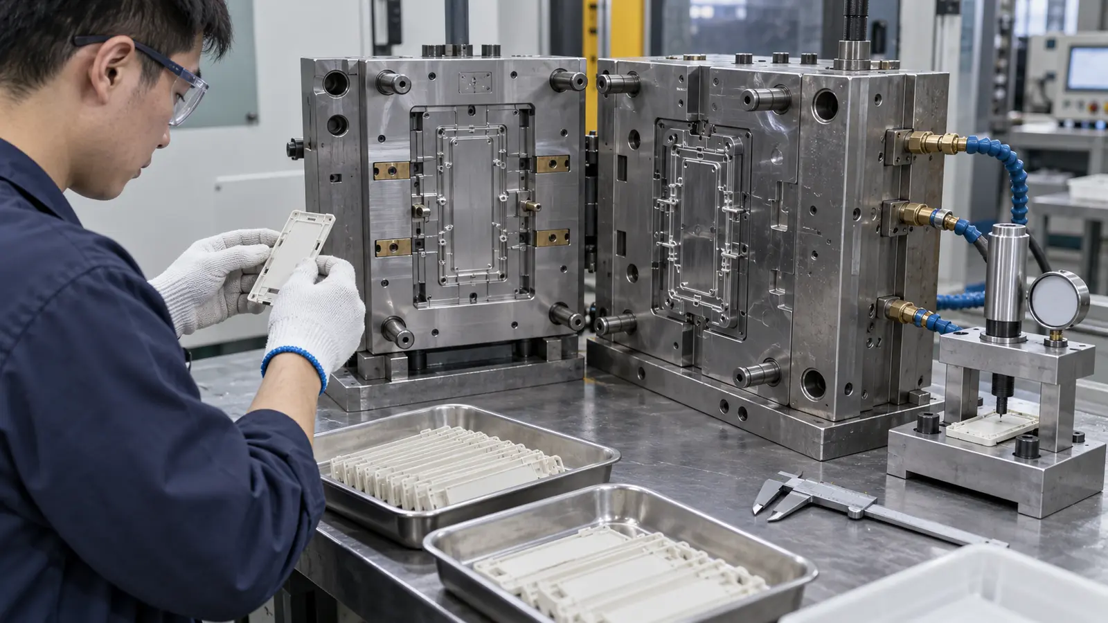
A simulation becomes useful when every important plot has a planned verification step. If the model predicts an end-of-fill air trap, the trial should inspect that location for burn marks and incomplete fill. If it predicts a weld line near a clip, the trial should test the clip under its real load rather than only judging the surface.
Keep model assumptions beside the trial record: material grade, mold temperature, gate layout, injection profile, cooling concept, and acceptance criteria. When the physical result differs from the prediction, review the input or tool condition before dismissing the analysis.
- List the predicted risk.
- State the physical observation that would confirm it.
- Define the tool or process change to test.
- Record the effect on fill, appearance, dimensions, and function.
An injection molding DFM analysis can frame those questions before the model is finalized. After sampling, the site’s quality control process is the natural next reference for inspection and repeatability requirements.
FAQ: Thin-Wall LCP Mold Flow
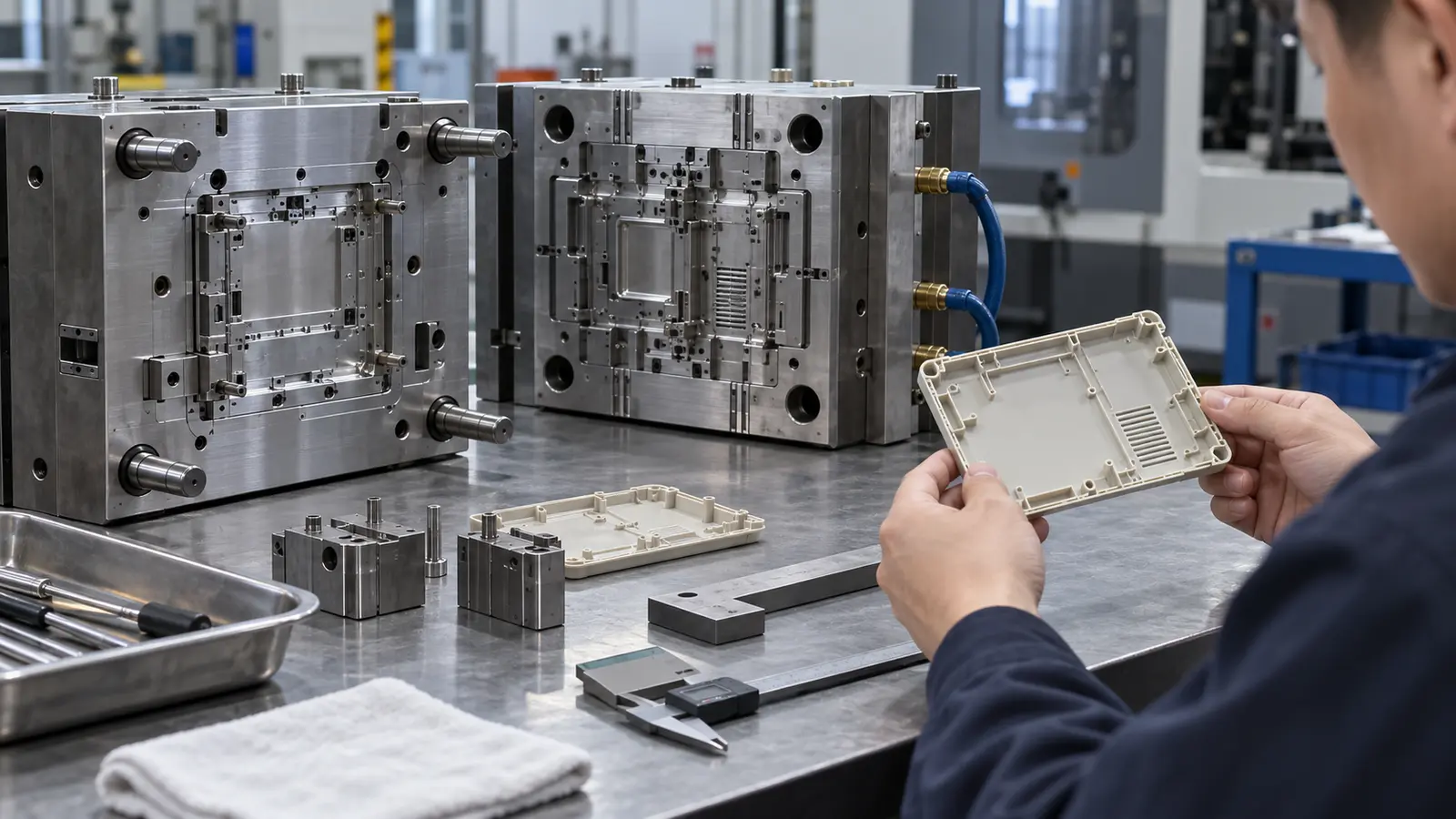
Is mold-flow analysis required for every LCP part?
No. It becomes more valuable when the wall is thin, the flow path is long, gate options are limited, or the cost of mold rework is high.
Can the model predict exact warpage?
It can indicate warpage trends and likely drivers, but exact results depend on material data, cooling, tool accuracy, process control, and measurement conditions.
What is the first result to review?
Start with fill feasibility and last-fill behavior, then check pressure, air traps, weld lines, orientation, cooling, and dimensional risk.