
Thiết kế ống dẫn sáng tốt vẫn có thể thất bại sau khi làm khuôn vì hiệu suất quang học chỉ là một phần của công việc. Chi tiết đúc cũng phải khớp với LED, vừa vặn trong vỏ, tháo khuôn mà không bị hư hại, giữ được căn chỉnh, tránh các vết cổng phun và vết đẩy lộ rõ, và duy trì ổn định qua quá trình lắp ráp. Một mô hình truy vết tia sáng có thể dự đoán đầu ra đạt yêu cầu trong khi chi tiết sản xuất thực tế lại cho thấy bề mặt mờ, điểm sáng chói hoặc nhiễu xuyên âm. Để thu hẹp khoảng cách đó, các quyết định về quang học, cơ khí và đúc phải dùng chung datum và bài kiểm tra nghiệm thu.
Những lỗi thường gặp
Các nhóm tối ưu hóa hình học trong suốt, rồi coi cổng phun, đường phân khuôn, chốt đẩy, các đặc điểm giữ cố định và xếp lớp PCB là những chi tiết thứ yếu. Những chi tiết đó lại quyết định liệu đường truyền quang học đã mô phỏng có tồn tại được qua quá trình đúc và lắp ráp hay không.
Trong bài viết này:
- Coi chi tiết là một đường truyền quang học
- Kiểm soát giao diện LED trước tiên
- Cho các đoạn uốn và đặc điểm bề mặt một nhiệm vụ duy nhất
- Giữ các yếu tố khuôn ngoài chức năng quang học
- Chặn nhiễu xuyên âm trước khi tăng công suất LED
- Xác nhận hệ thống đã lắp ráp
- Câu hỏi thường gặp
Ống dẫn sáng là một đường truyền quang học, không phải một thanh trong suốt
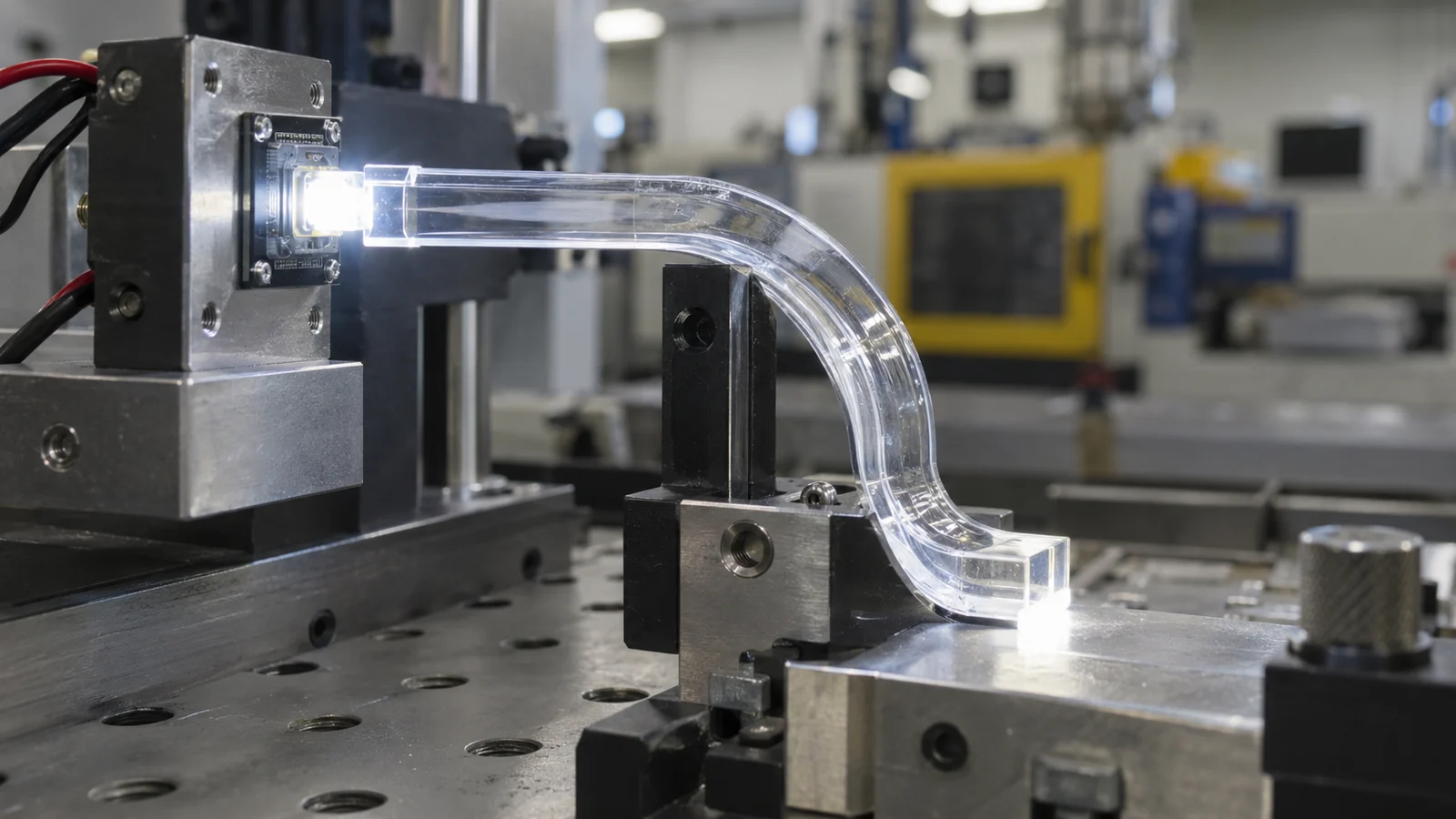
Ống dẫn sáng truyền ánh sáng từ nguồn đến bề mặt quan sát thông qua phản xạ nội toàn phần và trích xuất có kiểm soát. Hiệu năng của nó phụ thuộc vào nhiều yếu tố hơn là độ trong suốt. Hình học lối vào, tình trạng bề mặt, các đoạn uốn, tiếp xúc thành ống, các đặc điểm gắn kết và mặt thoát sáng đều thay đổi nơi ánh sáng truyền đi và nơi nó thoát ra.
Hãy bắt đầu bằng việc xác định người quan sát phải thấy gì. Một đèn báo trạng thái có thể cần một điểm sáng đồng đều từ nhiều góc nhìn. Một biểu tượng được chiếu sáng nền có thể cần khuếch tán được kiểm soát. Một đặc điểm chiếu sáng cạnh dài có thể cần các cấu trúc trích xuất chủ động giải phóng ánh sáng dọc theo chiều dài của nó. Đây là những nhiệm vụ quang học khác nhau và không nên dùng chung một hình học chung chung.
Tách vùng quang học khỏi vùng hỗ trợ cơ khí trên bản vẽ. Vùng quang học cần các kiểm soát về bề mặt và hình học gắn với đầu ra ánh sáng. Vùng hỗ trợ có thể mang các đặc điểm giữ cố định, lắp ráp và đẩy khuôn. Kết hợp cả hai chức năng trong cùng một khu vực nhỏ thường tạo ra những thỏa hiệp khó chẩn đoán sau khi làm khuôn.
Tổn thất ghép nối bắt đầu từ giao diện LED
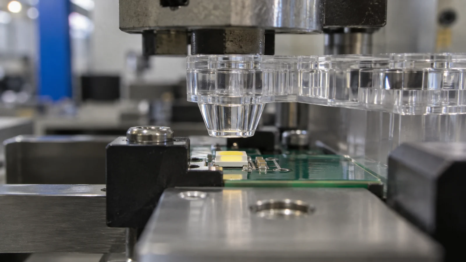
Mặt lối vào không thể thu nhận ánh sáng không bao giờ tới được nó. Do đó, chiều cao gói LED, diện tích phát sáng, góc nhìn, dung sai bo mạch và khe hở không khí giữa LED và ống dẫn nên được xử lý như một chuỗi dung sai duy nhất. Một ống dẫn sáng danh nghĩa được căn giữa có thể hoạt động kém khi PCB, vỏ và các đặc điểm giữ cố định bằng nhựa đúc dịch chuyển theo các hướng ngược nhau tại giới hạn dung sai của chúng.
Keep the entrance face large enough for the expected source and positional variation, but do not assume that a larger gap is harmless. Gap, angle and surface finish change how much light enters the pipe. A locating feature that references the enclosure while the LED references the PCB can create a hidden datum conflict. The design review should identify which component controls the final optical alignment.
Commercial light-pipe suppliers also pair geometry with particular LED arrangements rather than treating the pipe independently. Dialight’s LED indicator design guidance, for example, begins with layout alignment and source selection. A custom molded design needs the same system-level discipline.
Give Bends and Surface Features One Job
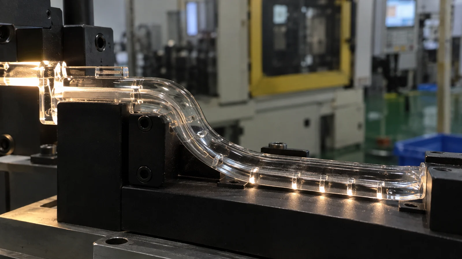
Every bend changes the incidence angles inside the part. A tight turn can let light escape, concentrate brightness on one side or create a visible hot spot. The solution is not always to add a texture. Texture, prism features and diffusing geometry intentionally disrupt the optical path; if they are placed without a defined extraction purpose, they can reduce useful output while only hiding the symptom.
Use smooth, gradual transitions where the design intends to preserve internal reflection. Reserve microfeatures or diffusion for locations where light must leave the pipe. Keep ribs, bosses and snap features away from critical reflection surfaces when possible, because their local thickness and shrinkage can distort the surface that carries the light.
A polished surface is not automatically correct everywhere. Entry and transport surfaces may need smooth replication, while the exit face may need a controlled texture or optical pattern. The drawing should state the function of each surface rather than apply one finish note to the complete component.
Tooling Details Can Undo the Optical Design
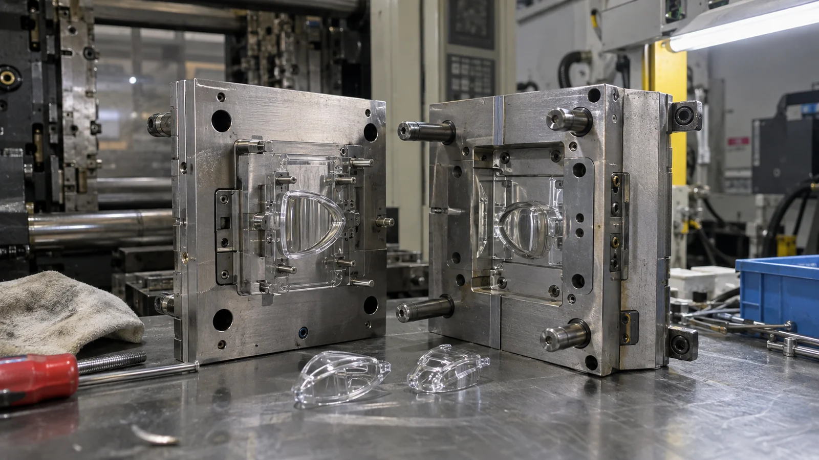
Mold construction determines where the design must accept a parting line, gate vestige, vent witness and ejection contact. Placing any of them inside a critical transport or viewing surface can scatter light or create a visible interruption. Moving them outside the optical zone may require a different draw direction, split or retention concept, so these decisions belong in early DFM—not after the optics are frozen.
Gate position affects more than cosmetics. It sets the flow direction, the highest-shear region and the way packing pressure reaches the part. A restrictive gate beside the light path can leave stress or a visible flow signature. A remote gate may improve appearance but create a longer flow path and weaker packing at the far end. In Ép phun quang học & trong suốt, the gate should be reviewed against optical function, flow balance and removal method together.
Ejection is another common blind spot. A long slender pipe can flex during release, while a broad viewing face can show stress or witness marks if ejection force is concentrated. Draft, polish direction and support during ejection must protect both geometry and optical surfaces.
Control Crosstalk Before Adding More LED Power
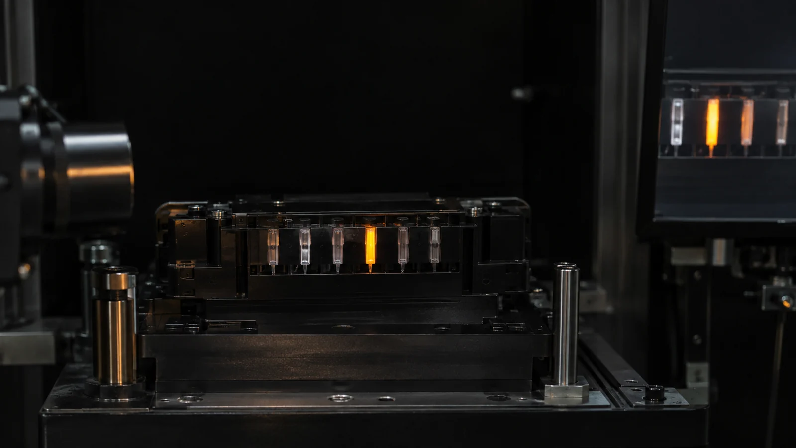
When adjacent indicators glow at the same time, increasing LED output usually makes the crosstalk more obvious. First identify whether light is escaping from the pipe, traveling through the clear mounting structure, reflecting inside the enclosure or entering the neighboring pipe at its source.
Opaque barriers, isolated holders and controlled gaps can block unwanted paths, but they also consume space and add assembly interfaces. A black housing around individual pipes is effective only when the barrier remains continuous after tolerance and assembly variation. Glossy internal walls can reflect light around a nominal barrier; matte dark surfaces may be more useful in those locations.
| Triệu chứng quan sát được | Evidence to collect | Likely review area |
|---|---|---|
| Bright entry, dim exit | Gap and alignment at LED | Coupling face and datum stack |
| Hot spot after a bend | Brightness map through the turn | Bend radius and surface continuity |
| Neighboring icon glows | One LED powered at a time | Barriers, holder and enclosure reflections |
| Cavity-to-cavity variation | Output by cavity and position | Tool replication, cooling and process balance |
Prototype the System, Not the Isolated Part
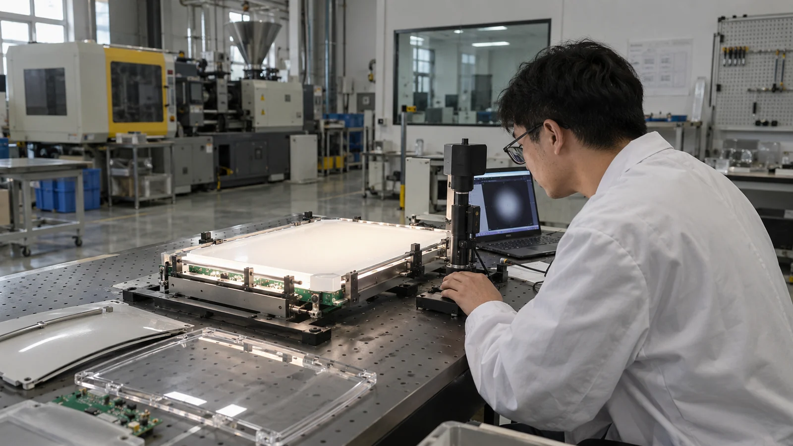
A loose light pipe held above a bench LED does not reproduce the final air gap, alignment, enclosure reflection or observer angle. Validation should use the intended LED, PCB, holder, enclosure and front panel whenever possible. Record both electrical input and optical output so a brighter LED is not mistaken for a better pipe.
Build the acceptance test around the product’s viewing condition. Useful outputs may include luminance at defined angles, uniformity across the exit face, color difference, crosstalk at neighboring indicators and retention after assembly. The exact metric depends on whether the device communicates status, illuminates a symbol or distributes light across a larger feature.
- Lock the LED part number, drive condition and PCB reference.
- Measure the assembled gap and alignment, not only CAD nominal values.
- Test multiple molded cavities and more than one production cycle.
- Inspect the gate, parting line, ejection and handling marks under the same lighting used for approval.
- Recheck performance after enclosure assembly and expected environmental exposure.
Material candidates should be screened at the grade level. Review PMMA optical molding considerations when transmission and weathering lead the decision, or polycarbonate grade requirements when impact and temperature resistance carry more weight.
Các câu hỏi thường gặp
Should a light pipe touch the LED?
Not automatically. The required gap depends on the LED package, entrance geometry, thermal and assembly conditions. The important requirement is a controlled, repeatable interface that remains inside the validated coupling range.
Why does the molded light pipe look dimmer than the prototype?
Check the LED alignment, air gap, molded surface condition, gate-related stress, bend geometry and enclosure losses. A machined or printed prototype may not reproduce the same surface replication, material, internal stress or assembly stack as the molded part.
Can texture improve light-pipe uniformity?
Texture can redistribute or extract light, but it also reduces light remaining in the pipe. Place it only where the optical model and physical test show that controlled extraction is needed.
What information should a light-pipe RFQ include?
Include the 3D part and assembly, LED datasheet and drive condition, PCB and enclosure stack-up, optical viewing requirements, material preference, annual volume, cosmetic zones and the intended optical acceptance test.