
Fundir fixadores metálicos, pinos eletrônicos ou barramentos de alta tensão diretamente em carcaças estruturais de plástico requer rigorosa gestão térmica e tempo de ciclo exato. A encapsulação perfeita de metal-plástico depende da execução de sequências de processamento repetíveis que previnam o dobramento do pino do núcleo, rebarbas de plástico ou rachaduras por tensão interna.
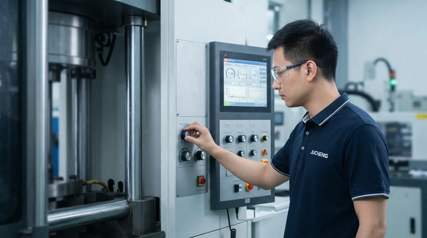
Compreender as etapas sequenciais no molde—desde o pré-aquecimento do metal bruto até a extração automatizada da peça por robô—permite que os técnicos de processamento estabeleçam janelas operacionais amplas e estáveis. Estabilizar os perfis de pressão da cavidade e controlar a reologia do fundido garante peso consistente da peça e resistência mecânica da junta. Este guia técnico analisa as sequências de etapas no molde, parâmetros de monitoramento do processo e critérios de seleção de prensa.
Índice
As 5 Etapas no Molde: Aquecimento, Posicionamento, Injeção, Compactação e Extração
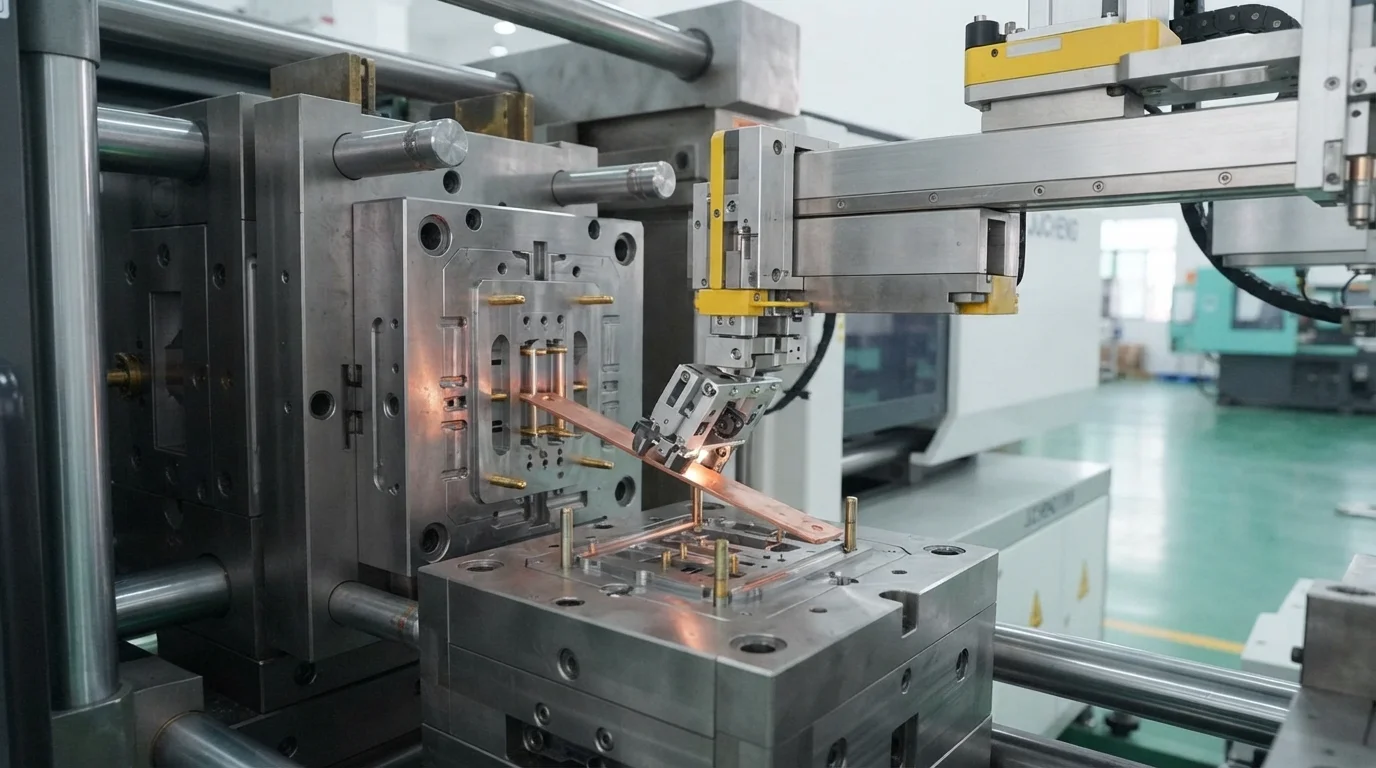
Executar um processo de moldagem por inserção estável requer sincronização precisa em cinco fases sequenciais de fabricação. A etapa um pré-aquece os insertos metálicos a 100°C para minimizar o choque térmico localizado quando a resina fundida entra em contato com o aço frio. A etapa dois carrega os latão ou cobre insertos pré-aquecidos nos pinos de localização do núcleo usando posicionamento manual ou automatizado carregamento robótico de insertos.
O estágio três injeta resina fundida em alta velocidade, preenchendo 95% do volume da cavidade antes de mudar para pressão de sustentação. O estágio quatro aplica pressão de compactação controlada, forçando plástico líquido para dentro de perfis metálicos serrilhados para solidificar sem marcas de afundamento. O estágio cinco abre as placas do molde, permitindo que os pinos ejetores empurrem o conjunto encapsulado para fora de forma limpa.
Estágios sequenciais de processamento no molde incluem:
- Pré-aquecimento do inserto metálico—Aquecer contatos metálicos reduz gradientes térmicos, prevenindo microtrincas nas paredes de polímero circundantes.
- Posicionamento do pino de núcleo—Fixar insertos metálicos sobre pinos de localização endurecidos garante orientação espacial exata.
- Preenchimento com controle de velocidade—Injetar material fundido sob controle de velocidade em malha fechada preenche cavidades complexas sem deslocar insertos não ancorados.
- Compactação por pressão e resfriamento—Aplicar pressão interna de compactação alimenta a contração volumétrica até que os canais de injeção congelem completamente.
- Ejeção robótica da peça—Extrair conjuntos acabados suavemente evita dobrar pinos de contato delicados durante a liberação do molde.
Controles de Moldagem Científica (CPK > 1,67) para Tolerâncias Repetíveis
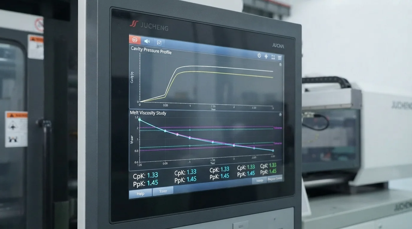
Estabelecer estabilidade de fabricação em alto volume depende de metodologias científicas de controle de processo. Monitorar transdutores de pressão de cavidade embutidos atrás de aços de fechamento fornece feedback em tempo real sobre a compressão do fundido. Transdutores de cavidade detectam mudanças sutis de viscosidade causadas por variações de lote de matéria-prima, prevenindo injeções curtas ou rebarbas antes que peças defeituosas sejam produzidas.
Conduzir estudos de reologia do fundido identifica a velocidade de preenchimento ideal onde a viscosidade do polímero permanece estável sob altas taxas de cisalhamento. Manter índices de capacidade de processo com CpK > 1,67 garante que dimensões críticas de fechamento permaneçam dentro de ±0,01 mm ao longo de 100.000 ciclos. Controlar variáveis no processo de moldagem por inserção é necessário para zero defeito. moldagem por inserção fabricação.
Seleção de Prensas: Máquinas de Injeção Verticais vs. Horizontais (15T a 3000T)
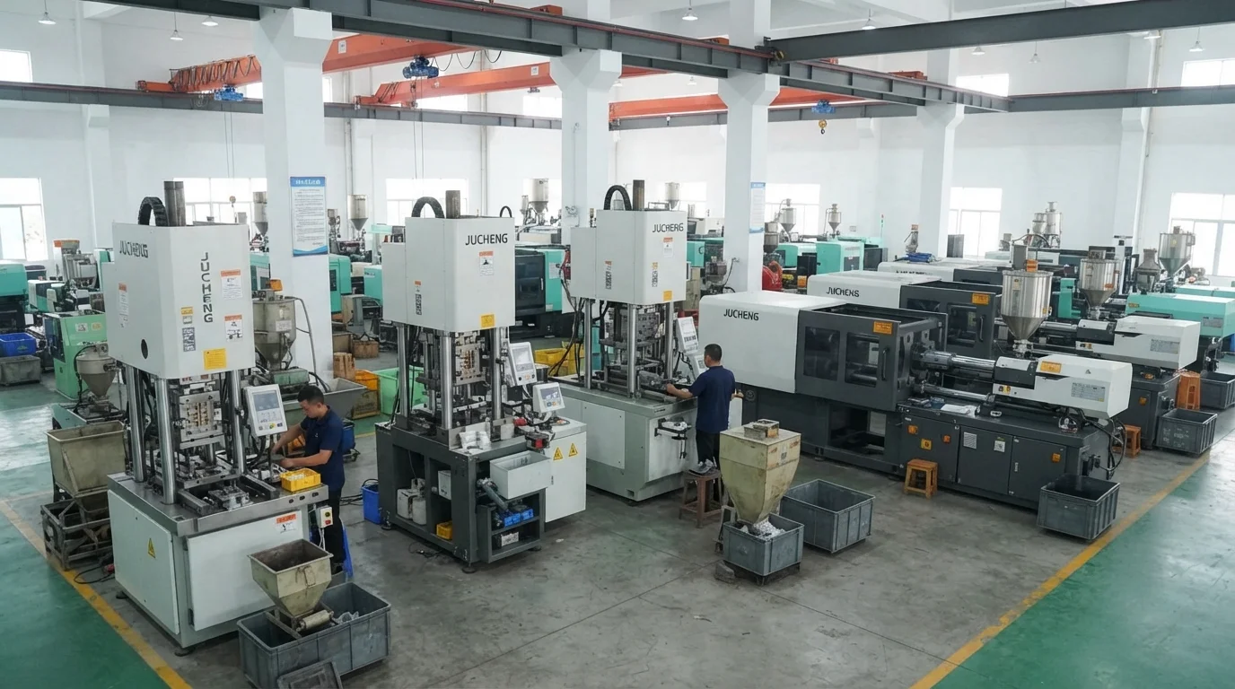
A seleção das configurações adequadas da máquina depende da geometria do inserto, da ergonomia de carregamento e dos volumes de produção anuais. Máquinas de injeção verticais com mesas rotativas alternadas são ideais para a colocação manual de insertos. A gravidade mantém insertos metálicos soltos com segurança na metade inferior do molde, eliminando riscos de queda do inserto durante o fechamento do molde.
Padrão Prensas de injeção horizontais equipadas com robôs articulados de 6 eixos se destacam em execuções de produção automatizada de alto volume. Ferramentas robóticas de fim de braço carregam pinos metálicos nos núcleos de moldes horizontais em segundos, maximizando o rendimento da máquina. A capacidade de tonelagem de fixação que varia de 15T a 3000T acomoda tanto conectores microeletrônicos quanto grandes tampas estruturais de baterias de VE.
| Arquitetura da Prensa de Injeção | Configuração de Fixação e Carregamento | Método de Colocação do Inserto | Principal Benefício de Fabricação |
|---|---|---|---|
| Prensa Vertical (Mesa Rotativa Alternada) | Fixação Vertical / Injeção Vertical | Colocação manual / Assistida por gravidade | Evita o deslocamento do inserto em layouts complexos de múltiplos pinos |
| Prensa Horizontal (EOAT Robótico) | Braçadeira Horizontal / Injeção Horizontal | EOAT de Robô Articulado de 6 Eixos | Produção automatizada de alto volume excedendo 100.000 peças |
| Prensa de Alta Tonelagem 3000T | Braçadeira Horizontal + Manifold Quente SVG | Carregador robótico de barramento pesado | Encapsula barramentos grandes (até 2,5m) sem linhas de solda |
Perguntas Frequentes (FAQs)
Por que é necessário pré-aquecer insertos metálicos durante o processo de moldagem por inserto?
Pré-aquecer insertos metálicos a 100°C reduz a diferença de temperatura entre o metal frio e o polímero fundido. Minimizar o choque térmico evita que a pele plástica se solidifique prematuramente, permitindo que as cadeias poliméricas esfriem uniformemente sem reter tensões residuais elevadas que causam rachaduras.
Quando as prensas de injeção verticais devem ser selecionadas em vez das prensas horizontais?
Prensas de injeção verticais com mesas rotativas alternadas são preferidas para insertos soltos ou complexos que exigem colocação manual. A gravidade mantém os insertos naturalmente na placa do molde inferior, evitando o deslocamento do inserto durante o fechamento do molde.
Como os transdutores de pressão de cavidade evitam injeções curtas durante a encapsulação de insertos?
Os transdutores de pressão de cavidade medem a pressão interna do fundido em tempo real durante o preenchimento e a compactação. Se a viscosidade da resina mudar ou um inserto bloquear o fluxo do fundido, o sensor detecta uma queda de pressão e aciona alarmes da máquina antes que peças com injeção curta saiam da prensa.