
Gate removal separates the molded part from its runner or removes the gate remnant left at the entry point. The objective is not simply to make the gate disappear: the finished edge must preserve fit, appearance, and function without cracking the part or leaving a sharp projection. Injection molded part gate removal methods should be selected from the gate geometry, resin behavior, production volume, and the drawing’s vestige limits.
Specify the gate vestige before selecting a tool
Gate vestige is the remaining mark or projection at the point where the gate was separated. Define its allowed height or profile, location, sharp-edge limit, and cosmetic status on the part drawing. A nonfunctional hidden edge and a visible sealing surface require different controls.
Then identify how the part is gated: edge, tab, fan, pin, hot-runner, or another arrangement. Gate size, orientation, and local wall thickness influence how separation behaves. Resin toughness, filler, temperature, and conditioning can also affect whether the gate cuts cleanly or tears into the part.
Compare separation approaches by control and volume

Manual cutting can be flexible when volumes are low or gates are easy to reach, but the result depends on operator technique, blade condition, and part support. A guided hand tool or fixture can make the cut location more repeatable. Automated cutters can support higher throughput when the part can be located consistently and the tool can access the gate without loading fragile features.
Some parts can separate through a designed breakaway gate or a degating feature, but this must be engineered and validated; an uncontrolled snap can propagate a crack into the product. Hot-runner systems may eliminate a conventional runner in some designs, yet still leave a gate vestige that requires consideration. The site’s gate removal process should be matched to the actual drawing and inspection requirement.
| Approach | Potential fit | Risk to control |
|---|---|---|
| Manual cut | Accessible gate, lower volume, flexible variants | Variation, slips, unsupported part |
| Guided fixture trim | Repeatable location and edge requirement | Fixture wear or incorrect seating |
| Automated cutting | Stable part location and recurring volume | Tool access, cycle consistency, part damage |
| Designed breakaway | Gate engineered for controlled separation | Cracking or inconsistent break plane |
Design the gate for removal, not only for filling
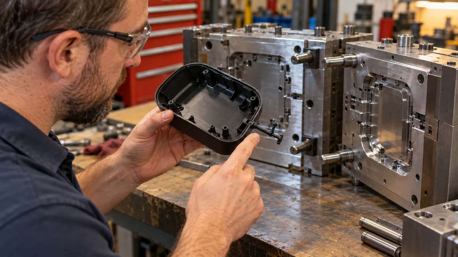
Gate design affects both cavity filling and downstream finishing. Place the gate where the vestige can be accepted, the cutter can reach, and the part can be supported during separation. Avoid putting a gate on a thin unsupported wall or next to a snap, seal, or cosmetic edge unless the removal method has been proven there.
Provide enough access for the selected tool and a clear part datum for any trimming fixture. If the gate location is hidden after assembly, still verify that the remnant cannot interfere with mating, wiring, fluid flow, or handling. Consider whether the part can be held without crushing or scratching its molded surface.
Verify the cut without damaging the part
Inspect the gate area for residual projection, gouging, whitening, cracks, sharp edges, and local distortion. If the gate is near a critical interface, include a fit or functional check in addition to visual review. Agree on lighting, viewing distance, and sample frequency where appearance acceptance is subjective.
- Define the finished edge: specify the allowed vestige and prohibited damage.
- Trial representative parts: include normal variation in resin, molding, and gate condition.
- Confirm support and access: check fixture seating and tool approach.
- Inspect the failure modes: look for cracks, whitening, burrs, and fit interference.
- Monitor tool wear: verify that a cutter or fixture remains within the acceptance plan.
If the gate repeatedly tears or leaves excess material, investigate gate dimensions, material behavior, part support, and cutting condition together rather than increasing force blindly.
الأسئلة الشائعة
Is gate removal the same as deflashing?
No. Gate removal separates the molded part from its designed feed point or trims its remnant. Deflashing removes unintended excess material at parting lines, vents, or other mold boundaries.
Can the gate vestige be invisible?
Not always. A flush or minimally visible result depends on the gate design, resin, part geometry, and removal method. The drawing should define an achievable appearance requirement.
Should gate removal be included in the part design review?
Yes. Gate position, cutter access, part support, and acceptance limits affect the mold and assembly design. Resolve them before production tooling is finalized.
Good gate removal is designed into the part: define the vestige, support the cut, and inspect the edge against the function it must preserve.